background image

       USER & PARTS MANUAL 

CS940 


15 


3


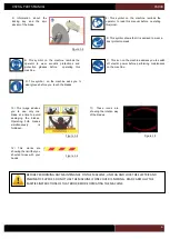
HANDLING AND UNPACKING 


To  handle  the  machine,  it 
is  necessary  to  use  a 
Forklift  equiped  with  forks 
of  minimum  115cm  lenght. 
The  weight of the machine 
is 167kgs. 
 
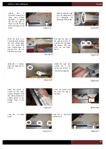
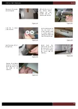
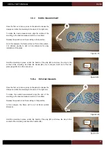
Locate  the  front  facing  of 
the crate, it is hold in place 
by special ears that can be 
bent  back  to  open  the 
door.  
 
Cut  the  straps  closing  the 
crate  and  remove  the  top 
cover and top belt (BT). 

With  the  help  of  a  flat 
screw driver, bent back the 
ears  to  be  able  to  remove 
the front panel of the crate. 
 
Pull  on  the  front  facing  to 
open it. 


Take 

care 

of 

not 

damaging  the  profiles 
which  are  stored  at  the 
back  of  the  saw,  remove 
them  before    introducing 
the 

forks 

under 

the 

machine. 


Figure 3-1


Figure 3-2


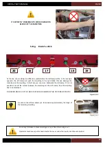
With  the  help  of  the 
crowbar,  remove  the  side 
panels of the crate. 


You  can  then  lift  the 
machine using the forklift. 
Insert  the  forks  at  the 
indicated  place  in  picture 
opposite.  


Figure 3-3


Figure 3-4


Figure 3-6


Pay  attention  not  to 
damage  the  scales  that 
are protuding from top of 
the  arm.  They  are  very 
fragile. 

 
Cut the schrink wrap film to 
extract  the  arms  of  the 
machine. 

Figure 3-5


Flat screw driver.   


Crowbar 

Protecting gloves  


Forklift 

BT 

Содержание CS 940

Страница 1: ...USER PARTS MANUAL Version 5 05 2017 Z27456 Version 1 07 2014 ...

Страница 2: ...m installation 20 4 C ELECTRIC CONNECTION 22 4 D PLUGING THE MACHINE TO THE AIR SOURCE 22 4 E DUST COLLECTOR CONNECTION 23 5 USING THE MACHINE 24 5 A STARTING THE MACHINE 24 5 B SAWING 25 5 B a Setting the horizontal clamps 25 5 B b Setting the vertical clamps optional 25 5 B c First cut 26 5 B d Inside measurement 27 5 B e External measure 27 5 B f Cut of the first piece 28 5 B g End of a stick 2...

Страница 3: ...EMENT PNEUMATIQUE 56 4 E ASPIRATION 57 5 UTILISATION 58 5 A MISE EN ROUTE 58 5 B SCIAGE 59 5 B a Réglage des presseurs horizontaux 59 5 B b Réglage des presseurs verticaux optionnels 59 5 B c Première coupe à gauche 60 5 B d Mesure fond de feuillure cote interieure 61 5 B e Mesure de la cote externe du cadre 61 5 B f Coupe du premier morceau 62 5 B g Fin de moulure 63 6 MAINTENANCE ENTRETIEN 65 6 ...

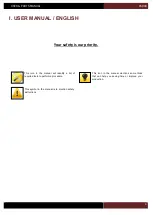
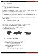
Страница 4: ...s our priority This icon in the manual mentions some tricks that can help you saving time or improve your production This icon in the manual will identify a list of required tools to perform a procedure This symbol in the manual is to mention safety instructions ...

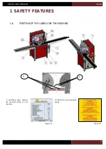
Страница 5: ...PARTS MANUAL CS940 5 1 SAFETY FEATURES 1 A POSITION OF THE LABELS ON THE MACHINE Figure 1 1 2 Information about pressure supply Figure 1 2 9 11 1 Identitying plate showing the technical datas of your machine ...

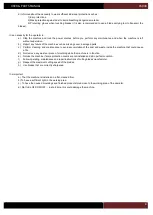
Страница 6: ... asks you to wear gloves before you touch the blades 3 Information about the locking key and the spin slocker of the blade Figure 1 3 10 This image advises you to use only one blade at a time to avoid damaging the blades Operating both blades simultaneously is forbidden Figure 1 4 Figure 1 5 11 These icons are showing the rotation way of the blades Figure 1 6 12 This marks are showing the limit th...

Страница 7: ... engage his hands in the clamp area nor in the cutting area behind the brushes blades are rotating even when returned to the top Do not use steel blades HS type Prior to any maintenance operation switch off electric and pneumatic supply by using and locking their switches Switch off the machine by using the electric contactor on the right side of the machine Only one person at a time should use th...

Страница 8: ...form cleaning and maintenance to avoid accumulation of the dust and waste inside the machine that could cause a fire d Not remove any waste or piece of moulding while the machine is in function e Not use the machine if some protection covers are not installed and all in perfect condition f Follow operating maintenance and repair instructions of cutting blades manufacturer g Respect the maximum cut...

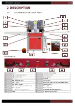
Страница 9: ... cabinet door 10 Control panel 11 Safety switch 12 Main circuit breaker can be locked with a locker 13 Air pressure regulator 14 Levelling feet x4 15 Air switch can be locked with a locker 16 Power light 17 Blade stop button 18 Blade start button 19 Left blade acknowledgment button 20 Right blade acknowledgment button 21 Pedal 22 Wastage compartment door 1 9 2 9 3 9 4 9 5 9 6 9 7 9 8 9 10 9 12 9 9...

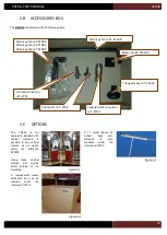
Страница 10: ...ck connector ref Z749 Connector ref Z556 US male connector ref Z701 The CS940 is not equiped in standard with vertical clamps It is possible to buy vertical clamps as an option under the reference Z28030 Using these vertical clamps will provide better holding of the moulding A 1 1 meter about 43 inches right arm extension is also available under the reference Z27970 Figure 2 1 Figure 2 2 A replace...

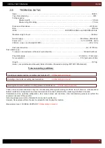
Страница 11: ...d Noise measuring conditions 1 metering at operator position not cutting dust collector off Véritas testing in process 9 metering at one meter not cutting dust collector on Véritas testing in process 9 metering at one meter machine in cutting process dust collector on Véritas testing in process These values are measured values they are not necessarily showing safe working conditions Even if there ...

Страница 12: ...USER PARTS MANUAL CS940 12 2 E CUTTING CAPACITY ...

Страница 13: ...USER PARTS MANUAL CS940 13 2 F NEEDED SPACE ...

Страница 14: ...is covered by a one year warranty parts and labor included Wearing parts and damaged parts due to bad use of the machine are not covered by the warranty Are considered as wearing parts waste support belts blades cardboard waste box and clamps extremities ...

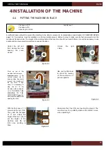
Страница 15: ...front panel of the crate Pull on the front facing to open it Take care of not damaging the profiles which are stored at the back of the saw remove them before introducing the forks under the machine Figure 3 1 Figure 3 2 With the help of the crowbar remove the side panels of the crate You can then lift the machine using the forklift Insert the forks at the indicated place in picture opposite Figur...

Страница 16: ...k the leveling of the machine as in picture opposite Figure 4 4 Figure 4 1 Unlock the left and front clamps that are keeping the cover closed Unlock the right clamp Pivot on top of the machine the front cover Important note if the vertical clamps are in down position they could prevent the opening of the top cover In that case it is necessary to plug the air to the machine refer to chapter I 4 D P...

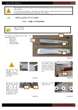
Страница 17: ...eir washers from the inside of the arm Discard the nut V3 that was just a spacer for transport to avoid damaging the scale Figure 4 9 Unlock the 3 screws ULF of 4 turns Figure 4 10 Figure 4 6 Pay attention during handling to not damaging the edge of the scales which are very fragile When installing the machine make sure the floor is flat and stable make sure your floor can support the weight of th...

Страница 18: ...k the V1 screw that was dismounted in Figure 4 12 Do not block the screw yet Figure 4 13 Still with the help of the second person to hold the arm put back the screws V2 and V3 do not block them Figure 4 14 Unlock the 3 screws under the right arm of 4 turns Slide the right arm profile 6 in the screw as shown in the picture opposite Figure 4 15 Slide the profile to center of the saw paying attention...

Страница 19: ... Figure 4 23 With a bubble level on the arm hold it in correct position while a second person is locking the front screw see following image Figure 4 24 Lock the screw V1 of the right arm Figure 4 25 Install back the washer and the nut of the screw V1 Lock the nut while holding the screw with an Allen key Figure 4 26 Remove the adhesive protection of the arm scale and stick it on the table of the ...

Страница 20: ...e 4 30 Remove the screw V6 in front of the machine keep that screw nut and washer as they will have to be installed in exact same position Figure 4 31 Start to install the left arm 7 taking care of not damaging the scale Figure 4 32 Figure 4 33 With the help of a second person install back the screw V6 but do not block the screw Figure 4 34 Still with the help of the second person put back both sc...

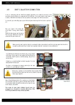
Страница 21: ...ocking the front screw see following pictures Figure 4 39 Lock the screws under the left arm Figure 4 40 Figure 4 41 Lock the screw V6 in the front of the machine Install the washer and nut on the screw V6 and lock the nut while holding the screw with an Allen key Figure 4 42 Remove the adhesive protection under the scale and stick it on the table of the saw Figure 4 43 A hole will receive the loc...

Страница 22: ...e plugging the machine on it Figure 4 45 The cable of the machine is contains 3 wires it must be connected to 240 volts single phase the earth must be connected to the yellow green wire The main contactor 12 must be in position 0 during the cabling The contactor rotating button BT allows to switch on the machine it can be locked with a locker in the 0 position Lock that button in 0 position before...

Страница 23: ...lot an outside starting device for a dust collector Contact your electrician dust collector supplier for more details about that function The saw is not designed to supply electricity to the dust collector it is just designed to pilot it Open the electrical cabinet of the machine on its right side The contactor CG can be used to pilot the dust collector The positions 5L3 and 6T3 are free to be use...

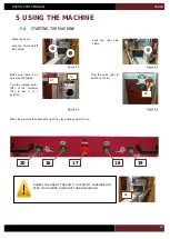
Страница 24: ... the contactor 12 to set it to I position 12 BT Figure 5 1 Close the cover Lock the front and left side clamp Lock the right side clamp Figure 5 2 Figure 5 3 VA Turn the valve VA to switch on the air Figure 5 4 When the machine is powered the light 16 see bellow must turn on DURING THE USE OF THE SAW IT IS STRICTLY FORBIDDEN TO PASS YOUR HANDS THROUGHT THE BRUSHES BS BS ...

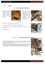
Страница 25: ...cut Repeat same sequence for the other vertical clamp 3 5 B1 Press on the pedal to release the clamps and to be able to introduce the moulding inside the machine Keep the pedal pressed during the adjustment of clamp s sequence 6 Figure 5 8 Proceed in the same way for the other horizontal clamp The moulding must be installed with the rebate facing to the blades The 2 horizontal clamps PH must be se...

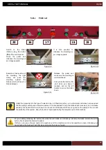
Страница 26: ...re 5 11 Figure 5 12 Adapt the mouvement to the type of material to be cut Plastic must be cut in a fast motion whereas hard wood and thick mouldings will require a slower movement It is also advised to help the blades back movement do not release suddenly the handle which would result in a shock and vibrations which are not good for the quality of the cut and the durability of the system Keep the ...

Страница 27: ...n place unlock the handle of the stop M3 and move the stop to the contact of the moulding lock back the handle M3 Go to chapter I 5 B f Cut of the first piece page 28 to do the second cut Figure 5 13 Figure 5 14 M3 Once the first cut is done press on the pedal to release the clamps and slide the moulding to the scale of the right arm To make the outside measurement align the end of the moulding to...

Страница 28: ...he cut Figure 5 19 Adapt the mouvement to the type of material to be cut Plastic must be cut in a fast motion whereas hard wood and thick mouldings will require a slower movement It is also advised to help the blades back movement do not release suddenly the handle which would result in a shock and vibrations which are not good for the quality of the cut and the durability of the system Keep the b...

Страница 29: ...s difficult to predict where the left clamp will be In the example opposite the left clamp will push the moulding to the right blade this can damage the machine and the moulding In that case you can move backwards the left clamp if it is not possible to avoid the contact between the moulding and the left clamp then the moulding has to be discarded DO NEVER MAKE A CUT IN THE SITUATION AS SHOWN IN T...

Страница 30: ...CS940 30 In case of a trouble press the red button 17 Then before any maintenance switch off and lock the main contactor and the air switch see page 22 Operation of the machine should be done only by one person at a time ...

Страница 31: ...in electrical contactor 12 and the air rotating switch 15 and lock it with a locker During that operation it is important to wear protecting gloves to avoid personal injuries Figure 6 2 Keep the pedal pressed and unlock the left and front cover clamps Still with the pedal pressed unlock the right clamp Figure 6 3 Allen key N 6 Protecting gloves Allen key N 10 Press the pedal to release the clamps ...

Страница 32: ...he handle to get the blade in down position With your other hand unlock the screw V8 Note The right blade screw has reverse threads while the left blade is a regular thread Pull the key to you to unlock those screws With one hand hold the blade in place so it doesn t fall down and remove the screw V8 Hold the flange in place with your finger to avoid it falling down Remove the flange and the blade...

Страница 33: ...ing system which makes the rotation of the blades difficult It is normal to feel some resistance when trying to rotate the blades by hand Figure 6 11 Figure 6 12 V7 Close back the cover and lock its 3 clamps Your machine is equiped with a waste support When it is damaged the waste will crack before the end of the cut and cause a crack at the bottom of the moulding To replace it unscrew the screw V...

Страница 34: ...e needed Before performing any maintenance switch off the main electrical contactor 12 and the air rotating switch 15 and lock it with a locker Your machine is equiped with a waste box reference Z27210 Its access is protected by a front door Pull on the handle of the door to open it Pull the box out of the machine and clean it Put back the box inside the machine It is strictly forbidden to use the...

Страница 35: ...clamps are well set The waste support is damaged The blade was installed in reverse way One belt is damaged and is also making noise Your cutting speed is not adapted to the material to be cut the plastic requires a fast speed hard wood and large mouldings will require a slower speed Moulding is wrapped or bent L7 One blade is not back up and the confirmbutton is not pressed L2 Both blades are not...

Страница 36: ... clamps and engaging when you release the pedal Switch on the blades lift the front cover of 10 centimeters only Blades must stop in less than 10 seconds For your safety do not open compltly the front cover when the blades are rotating do not engage your hands under the side brushes of the front cover Switch on the blades switch off the air blades must stop in less than 10 seconds If the machine d...

Страница 37: ...USER PARTS MANUAL CS940 37 ...

Страница 38: ...e icône dans le manuel vous signale une astuce susceptible de vous faire gagner du temps ou d améliorer votre production Cette icône dans le manuel vous permet de connaître la liste des outils nécessaires pour effectuer une procédure Cette icône dans le manuel met l accent sur un point important relatif à la sécurité ...

Страница 39: ... EMPLACEMENT DES ETIQUETTES DE SECURITE SUR LA MACHINE Figure 1 1 2 Information sur la pression d air et coupure de l alimentation électrique Figure 1 2 9 11 1 Plaque d identité de votre CS940 informations sur les caractéristiques techniques de la machine ...

Страница 40: ...on sur les lames de scies 8 Ce marquage sur la machine vous informe sur l obligation de couper l alimentation électrique au sectionneur avant d effectuer une opération de maintenance où une réparation 3 Information sur l emplacement de la clé de desserrage des lames et le verrou d immobilisation de la lame Figure 1 3 10 Ce marquage sur la machine vous informe sur le risque de casse de lames Figure...

Страница 41: ...uits et les surcharges Il convient que la protection soit généralement assurée par la coupure automatique de l alimentation électrique de la machine par le fonctionnement d un dispositif de protection installé par l utilisateur sur la ligne alimentant la machine EN60204 1 2006 Article 7 1 C CE QU IL NE FAUT PAS FAIRE En aucun cas l opérateur ne doit engager les mains dans la zone d action des véri...

Страница 42: ...ergie fermées et cadenassées pour toutes les interventions d entretien de maintenance et lorsqu elle est laissée sans surveillance h De signaler les défaillances de la machine y compris des protecteurs ou des lames dès leur découverte i D adopter des procédures de sécurité pour le nettoyage la maintenance d enlever les copeaux et la poussière régulièrement pour éviter tout risque d incendie j De n...

Страница 43: ...armoire électrique 10 Tableau de commandes 11 Verrou de sécurité 12 Sectionneur général cadenassable 13 Détendeur d air comprimé 14 Pieds de mise à niveau écrous de blocage x4 15 Vanne d air cadenassable 16 Voyant machine prête 17 Bouton d arrêt des lames 18 Bouton de mise en rotation des lames 19 Bouton autorisation coupe gauche 20 Bouton autorisation coupe droite 21 Pédale 22 Porte d accès au ba...

Страница 44: ...ide ref Z749 Embout cannelé ref Z556 Embout male US ref Z701 La CS940 est livrée en standard non équipée de presseurs verticaux Il vous est possible de les acquerir en commandant la référence Z28030 L utilisation de ces presseurs permet un meilleur maintien des moulures Il est possible d équiper la CS940 d une rallonge de table droite de 1 1mètres environ 43 pouces Elle est disponible sous la réfé...

Страница 45: ... l opérateur machine à vide système d aspiration désactivé Test Véritas en cours 9 Points de contrôle à un mètre surface de référence machine à vide système d aspiration activé Test Véritas en cours 9 Points de contrôle à un mètre surface de référence machine en charge système d aspiration activé Test Véritas en cours Les valeurs données sont des niveaux d émission et pas nécessairement des niveau...

Страница 46: ...USER PARTS MANUAL CS940 46 2 E CAPACITE DE COUPE ...

Страница 47: ...USER PARTS MANUAL CS940 47 2 F PLAN D ENCOMBREMENT ...

Страница 48: ...résence des vérins de maintien et des lames de scie en rotation dans leur position de repos haute 2 H GARANTIE La présente machine est garantie un an pièces et main d oeuvre comprises Les pièces d usure et celles endommagées suite au non respect des consignes du présent manuel sont exclues de la garantie Sont considérées comme pièces d usure les pièces suivantes martyr de coupe courroies lames car...

Страница 49: ...pour pouvoir extraire la façade Oter la face avant de la caisse Prenez garde à ne pas endommager les profilés qui sont stockés derrière la machine dans la caisse Figure 3 1 Figure 3 2 A l aide d un pied de biche en prenant garde à ne pas endommager la machine arracher les cotés de la caisse Vous pouvez ensuite lever la machine à l aide d un chariot élévateur en introduisant les fourches aux endroi...

Страница 50: ...chine comme illustré ci contre Figure 4 4 Figure 4 1 Dégrafer la grenouillère gauche ainsi que celle en façade verrouillant le capot Dégrafer la grenouillère de droite puis ouvrir le capot Basculer le capot sur le dessus de la machine Nota si les presseurs verticaux sont en position basse ils empêchent l ouverture du capot Il faut alors brancher l air voir chapitre 4 D BRANCHEMENT PNEUMATIQUE page...

Страница 51: ... V2 et V3 ainsi que leurs rondelles à l intèrieur du bras droit L écrou de V3 ne sera plus utile il sert d entretoise pour le transport afin de ne pas endommager le règlet de mesure avec la vis Figure 4 9 Deserrer les 3 vis ULF ci contre de 4 tours Figure 4 10 Figure 4 6 Prendre garde à ne pas écorner les règlets qui dépassent des deux bras Lors de l installation de la machine assurez vous que le ...

Страница 52: ...igure 4 8 Ne pas bloquer cette vis Figure 4 13 Toujours avec l aide d une personne pour maintenir le bras remettre en place les vis V2 et V3 sans les bloquer Figure 4 14 Desserrer les 3 vis sous le bras de 4 tours Glisser le profilé droit 6 dans la vis comme ci contre Figure 4 15 Puis le glisser vers le centre de la machine comme ci contre La rainure du bas du profilé doit glisser dans les vis ULF...

Страница 53: ...4 23 A l aide d un niveau à bulle controler le niveau du bras Maintenir le bras au bon niveau pendant qu une seconde personne bloque la vis de façade voir figure suivante Figure 4 24 Bloquer la vis V1 du bras droit en façade Figure 4 25 Monter la rondelle et l écrou sur la vis V1 Bloquer l écrou tout en maintenant la vis avec une clé Allen Figure 4 26 Enlever la protection sous le réglet et coller...

Страница 54: ...es rondelles Cette vis doit être conservée pour être remise à cette place une fois le bras monté Figure 4 31 Présenter le bras gauche 7 en prenant garde de ne pas endommager l extrémité du règlet Figure 4 32 Figure 4 33 Avec l aide d une deuxième personne pour soutenir le bras repositionner la vis V6 sans la bloquer Figure 4 34 Toujours avec l aide d une deuxième personne pour soutenir le bras rep...

Страница 55: ...au du bras et le maintenir jusqu au verrouillage de la vis de facade voir figures suivantes Figure 4 39 Bloquer les vis sous le bras gauche Figure 4 40 Figure 4 41 Bloquer la vis V6 de façade Positionner écrou et rondelle sur la vis V6 et bloquer l écrou tout en maintenant la vis avec la clé Allen Figure 4 42 Décoller la protection sous le réglet et coller celui ci Figure 4 43 Un orifice dans ce b...

Страница 56: ...jaune Le sectionneur général 12 doit être en position 0 lors du raccordement Le bouton rotatif BT permet la mise sous tension de la machine celui ci peut être verrouillé en position 0 à l aide d un cadenas Cette démarche est impérative pour la sécurité de l opérateur lorsqu une opération de maintenance doit être faite 12 BT Sur le coté droit de la machine derrière l armoire électrique est installé...

Страница 57: ...sitif de démarrage pour votre aspirateur Consultez votre électricien fournisseur d aspirateur pour plus de détails sur la démarche à suivre La scie ne dispose pas d une prise d alimentation pour l aspirateur elle peut simplement le piloter Ouvrir l amoire électrique de la machine Le contacteur CG peut être utilisé pour piloter l aspirateur les bornes 5L3 et 6T3 sont vacantes et donc utilisables po...

Страница 58: ...sition I 12 BT Figure 5 1 Fermer le capot Verrouiller la grenouillère gauche ainsi que celle en façade verrouillant le capot Verrouiller la grenouillère de droite Figure 5 2 Figure 5 3 VA Tourner la vanne VA afin d alimenter la machine en air Figure 5 4 Lorsque la machine est sous tension le voyant 16 voir ci dessous doit s allumer DURANT L UTILISATION DE MACHINE IL EST STRICTEMENT INTERDIT DE FRA...

Страница 59: ...êmes conditions pour le presseur gauche M1 CH B1 Appuyer sur la pédale afin de liberer les presseurs et pouvoir ainsi introduire la moulure dans le carter de coupe Garder la pédale enfoncée durant toute les phases de réglage des presseurs verticaux optionnels et horizontaux 6 Figure 5 8 Procéder de même pour le presseur horizontal de l autre coté Placer sur la table de travail en la présentant par...

Страница 60: ...bouton 19 et le maintenir enfoncé puis tirer la poignée gauche pour faire votre coupe Figure 5 11 Figure 5 12 Adaptez votre mouvement au matériau à couper le plastique demandera un mouvement rapide tandis qu un bois dur ou une moulure large demanderont un mouvement lent De même ne relâchez pas la poignée pour retourner la lame en position haute il vous est demandé d accompagner le mouvement de ret...

Страница 61: ...position desserez la manette M3 de la butée et amenez la en contact avec la moulure Bloquer ensuite la butée à l aide de la poignée M3 Passez à l étape II 5 B f Coupe du premier morceau page 62 pour faire la coupe de votre premier morceau Figure 5 13 Figure 5 14 M3 Une fois votre première coupe gauche réalisée appuyez sur la pédale pour libérer les presseurs et glissez votre moulure sur la table P...

Страница 62: ...ement rapide tandis qu un bois dur ou une moulure large demanderont un mouvement lent De même ne relâchez pas la poignée pour retourner la lame en position haute il vous est demandé d accompagner le mouvement de retour de la poignée pour éviter tout choc ou vibration qui pourrait à termer affecter la qualité du travail rendu ou la fiabilité de la machine Conserver la bouton 20 enfoncé pendant tout...

Страница 63: ... presseur gauche va repousser celle ci vers la lame de droite ce qui peut endommager la moulure et les lames de la machine Il faut donc soit reculer le presseur gauche pour empêcher son contact avec la moulure soit chuter le morceau de baguette NE JAMAIS FAIRE UNE COUPE AVEC LE PRESSEUR DANS LA POSITION CI CONTRE Figure 5 20 Figure 5 21 Un règlet sur le coté gauche de la machine vous permet de mes...

Страница 64: ...st formellement interdit de couper plusieurs longueurs de moulure à la fois en les empilant ou l une devant l autre En aucun cas l opérateur ne doit engager les mains à l intérieur du carter principal au delà des bandes de sécurité jaunes rouges sous peine de coupures graves Pendant l utilisation de cette machine le poste de travail ne doit pas être occupé par plus d une personne Celle ci à la res...

Страница 65: ...neumatiques de la machine en verrouillant le sectionneur général 12 et la vanne 15 à l aide de cadenas Pendant cette opération nous vous conseillons de mettre des gants pour manipuler les lames d une part et éviter de s accrocher les mains d autre part Figure 6 2 Tout en maintenant la pédale enfoncée dégrafer la grenouillère gauche ainsi que celle en façade verrouillant le capot Dégrafer la grenou...

Страница 66: ...a lame De l autre main débloquer la vis de lame V8 Nota le sens de desserrage des vis des lames est le même que le sens de rotation des lames La lame droite comporte un pas inversé la lame de gauche un pas conventionnel Tirer la clef vers vous pour desserrrer D une main maintenir la lame afin d éviter qu elle ne tombe de l autre oter la vis V8 Maintenir le flasque avec un doigt afin d éviter qu il...

Страница 67: ...veau la vis V7 et vérifier que la lame sera bien libre de tourner Nota les moteurs sont équipés d un frein qui rend leur rotation difficile à la main Figure 6 11 Figure 6 12 V7 Refermer la capot et verrouiller ses grenouillères Votre machine est équipée d un support de chute Lorsque celui est trop endommagé la chute va tomber avant la fin de sa coupe et causer une casse de la partie infèrieure de ...

Страница 68: ...mmagés contacter votre revendeur pour les obtenir Pour toute opération d entretien de réglage ou de réparation mettre hors service les circuits électriques pneumatiques de la machine en verrouillant le sectionneur général 12 et la vanne d air 15 à l aide de cadenas Votre machine est équipée d un bac à chutes référence Z27210 Son acces est protégé par une porte Ouvrir celle ci Tirer le carton hors ...

Страница 69: ...support de chute est trop âbimé La lame est montée à l envers Une courroie est âbimée et fait du bruit Votre vitesse de coupe est inadaptée aller vite pour du plastic et plus doucement sur un bois dur ou une baguette large La moulure est tordue ou voilée L7 Une lame n est pas en position haute et son bouton de validation n est pas enfoncé L2 les 2 lames ne sont pas en position haute Si une lame ne...

Страница 70: ...eurs horizontaux et verticaux optionnels s activent bien lors du relâchement de la pédale Mettre les lames en rotation soulever le capot d une dixaine de centimetres les lames doivent s éteindre en moins de 10 secondes Pour votre sécurité ne pas ouvrir complètement le capot lorsque les lames tournent ne pas passer les mains au delà des brosses du carter de protection Mettre les lames en rotation c...

Страница 71: ...USER PARTS MANUAL CS940 103 V CERTIFICATE CERTIFICAT DE CONFORMITE ...

Страница 72: ...USER PARTS MANUAL CS940 104 ...

Отзывы: