background image

IOM-6987

3

A. General:

1.  Maintenance procedures hereinafter are 

based upon removal of the regulator unit from 
the pipe line where installed.

2.  Owner should refer to owner's procedures for 

re mov al, handling, cleaning and disposal of 
nonreusable parts, i.e. gaskets, etc.

3.  Refer to Figure 2 for basic regulator parts.

B.  Diaphragm Replacement:

1.   For regulators with NPT end connections 

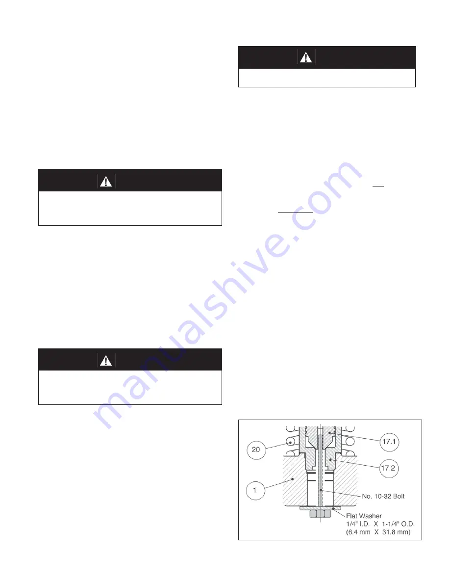
only, fabricate the special tool de scribed 
in Figure 1.  Rotate the No. 10-32 bolt CW 
to col lapse the piston spring (20).  This will 
hold the renewal unit (17) in place during 
dis as sem bly.  For all other end con nec tion 
options, proceed with Step 2.

2.  Securely install the body (1) in a vise with the 

spring chamber (2) directed upwards.

3.  Loosen the adjusting screw lock nut (5) and 

rotate the ad just ing screw (17) CCW until 
re moved from the spring cham ber (2).  

SECTION VI

VI.    MAINTENANCE

4.  Draw or em bed a match mark on the body (1) 

and spring chamber (2) flanges.

5.  If the special tool in Figure 1 is not being used, 

the piston spring (20) is always under ten sion.  
Therefore remove all flange bolts (13) 
except two located on opposite sides.  Turn 
remaining two flange bolts (13) CCW using 
even in cre ments.  The piston spring (20) will 
force the body (1) and spring cham ber (2) to 
separate. 

6.  Remove spring chamber (2), spring buttons 

(4), range spring (6), ball bearing (9),          
pressure plate (8), diaphragms (10), and     
diaphragm gasket (11).   

7.  Inspect pressure plate (8) for de for ma tion due 

to over-pressurization. If de formed, re place.

8.  Clean all parts to be reused according to 

own er's procedures.


NOTE:


On reg u la tors 

orig i nal ly sup plied as “spe cial cleaned”, 
Op tion-55, main te nance must in clude a 
level of clean li ness equal to Cash co’s 
clean ing stan dard #S-1134.  On reg u la tors 
orig i nal ly sup plied as “spe cial cleaned”, 
Op tion-56, main te nance must in clude a level 
of clean li ness equal to Cash co’s clean ing 
stan dard #S-1542. Con tact fac to ry for details.

SECTION V

2.  If the reg u la tor and system are both to be 

shut down, slowly close the inlet (upstream) block 
valve. Close the outlet (downstream) valve only if 
regu la tor re moval is required.

V. SHUTDOWN

1.  On systems with a bypass valve, and where 

sys tem pres sure is to be maintained as the 
regu la tor is shut down, slowly open the bypass 
valve while closing the inlet (upstream) block 
valve. Fully close the inlet (up stream) block valve. 
(When on bypass, the system pressure must be 
con stant ly observed and manually reg u lat ed. 
Close the outlet (down stream) block valve.

Figure 1: 

  Special tool for collapsing piston spring (20).

          CAUTION

Do not walk away and leave a bypassed reg u la tor 
un at tend ed!

          WARNING

SYSTEM UNDER PRESSURE. Prior to performing any 
main te nance, isolate the regulator from the system 
and relieve all pressure. Failure to do so could result in 
personal injury.

          WARNING

SPRING UNDER COMPRESSION. Prior to removing flange 
bolts, relieve spring compression by backing out the ad-
justing screw. Failure to do so may result in flying parts 
that could cause personal injury.

Содержание 6987

Страница 1: ...s continuous such that shutdown is not readily accomplished it is recommended that an inlet block valve outlet block valve and a manual bypass valve be installed 3 Pipe unions should be installed to allow removal from piping 4 An inlet pressure gauge should be located approximately ten pipe diameters upstream and within sight An outlet pressure gauge is optional 5 All installations should include ...

Страница 2: ...ge spring at maximum flow the inlet pressure should not exceed 1 5 x 100 psig 6 9 Barg or 150 psig 10 3 Barg If it does consult factory 12 Increase flow to maximum level if possible Inlet upstream or P1 pressure should fall off Readjust setpoint as necessary at the normal flow rate 1 Start with the block valves closed A bypass valve may be used to maintain inlet pressure in the upstream system wit...

Страница 3: ...ket 11 7 Inspectpressureplate 8 fordeformationdue to over pressurization If deformed replace 8 Clean all parts to be reused according to owner s procedures NOTE On regulators originally supplied as special cleaned Option 55 maintenance must include a level of cleanliness equal to Cashco s cleaning standard S 1134 On regulators originally supplied as special cleaned Option 56 maintenance must inclu...

Страница 4: ...ve the renewal unit 17 2 Remove the piston spring button 17 3 piston 17 1 with piston o ring 19 and the piston spring 20 3 Remove the cylinder 17 2 by turning CCW 4 Inspect seating surfaces of the piston 17 1 and cylinder 17 2 If necessary relap the seating surface or replace renewal unit 17 5 Clean all parts to be reused according to owner s procedures NOTE On regulators originally supplied as sp...

Страница 5: ...range spring screwing out CCW of adjustingscrewdoesnotallowbringingpressurelevel to a stable and proper level C Replace range spring with proper lower range Contact factory D Too much proportional band rise D1 D2 Review P B rise expected Contact factory E Restricted diaphragm movement E Ensure no moisture in spring chamber at temperatures below freezing Ensure no dust or debris entering vent openi...

Страница 6: ...mn A reflectminimum parts required for inspection and rebuild Soft Goods Kit Those in column B include minimum trim replacement parts needed plus those Soft Goods parts from column A If the BOM is not available refer to the cross sectional drawings included in this manual for part identification and selection ALocalSalesRepresentativewillprovidequotation for appropriate Kit Number Price and Availa...

Страница 7: ...ew Lock Nut 6 Range Spring 7 Diaphragm Ring upper range springs only See Figure 3 8 Pressure Plate 9 Ball Bearing 10 Diaphragms 11 Diaphragm Gasket 13 Flange Bolts 17 Renewal Unit 17 1 Piston 17 2 Cylinder 17 3 Piston Spring Button 19 Piston o ring 20 Piston Spring 24 Pipe Plug 7 8 9 4 17 3 10 19 Figure 3 Basic Model 6987 Metal Seat Range Springs from 200 psig to 800 psig ITEMS NOT SHOWN 16 Name P...

Страница 8: ...dual Essential Health and Safety Requirements are listed in Table 1 Table 2 lists all of the models and options that were evaluated and along with their evaluation Models and options not listed in Table 2 should be assumed to not have been evaluated and therefore should not be selected for use in a potentially explosive environment until they have been evaluated Standard default options for each l...

Страница 9: ...llow the same requirements for the piping system Also see item 30 in Table 1 2 The system designer and users must take precautions to prevent rapid system pressurization which may raise surface temperatures of system components and tubing due to adiabatic compression of the system gas 3 Heating systems installed by the user could possibly increase the surface temperature and must be evaluated by t...

Отзывы: