IOM-123-1+6 +S DIFF
7
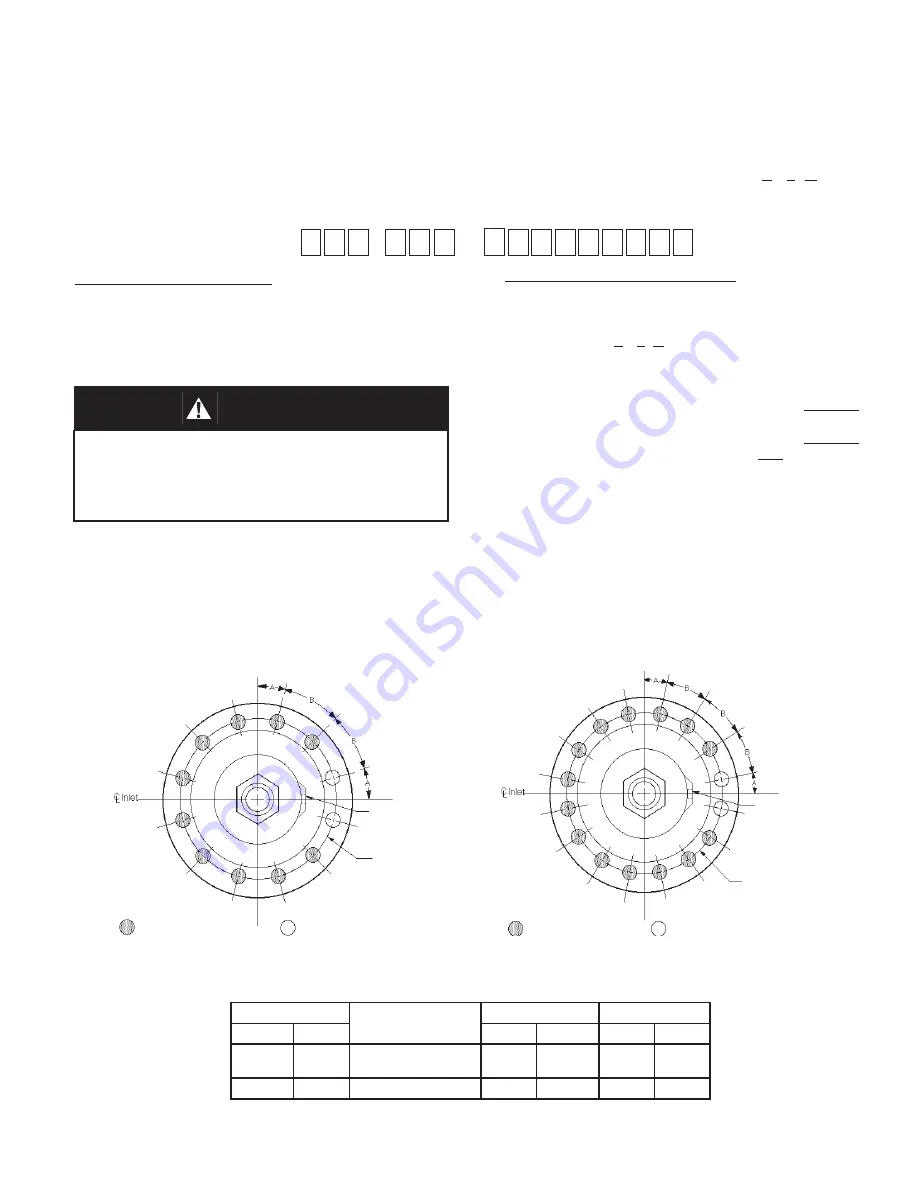
POSITION OF MOUNTING BRACKET STUDS
SECTION VIII
Figure 4: 1-1/2" (DN40) Body Size
Figure 3: 1/2" & 3/4" (DN15 & DN20) Body Sizes
Bolt Circle
1/2" (DN15) NPT
Loading
Pressure
Connection
Bolt Circle
Position of Longer Studs
(41,42) used for mounting
customer supplied bracket.
Position of two "Short" Cap
Screws (7,30) must straddle
1/2" (DN15) NPT Loading
Pressure Connection.
1/2" (DN15) NPT
Loading
Pressure
Connection
Position of Longer Studs
(41,42) used for mount-
ing customer supplied
bracket.
Position of two "Short" Cap
Screws (7,30) must straddle
1/2" (DN15) NPT Loading Pres-
sure Connection
Body SIze
No. of 1/2" (12.7 mm)
Dia. Bolt Holes
Bolt Circle
Position
in
(DN)
in
(mm)
A
B
1/2", 3/4",
1"
(15, 20,
25)
12
6-1/4"
(159 mm)
15°
30°
1-1/2"
(40)
16
7-1/2"
(191 mm)
11.25°
22.5°
NEW REPLACEMENT UNIT:
Contact your local Cashco, Inc., Sales Rep re sen-
ta tive with the Serial Number and Product code.
With this information they can provide a quotation
for a new unit including a complete description,
price and availability.
–
7
–
VIII. ORDERING
INFORMATION:
NEW REPLACEMENT UNIT vs PARTS "KIT" FOR FIELD REPAIR
To obtain a quotation or place an order, please retrieve the Serial Number and Product Code that was stamped
on the metal name plate and attached to the unit. This information can also be found on the Bill of Material
(parts list) that was provided when unit was originally shipped.) (Serial Number typically 6 digits). Product Code
typical format as follows: (last digit is alpha character that re
fl
ects revision level for the product).
CAUTION
Do not attempt to alter the original construction of any
unit without assistance and approval from the factory.
All purposed changes will require a new name plate
with appropriate ratings and new product code to
accommodate the recommended part(s) changes.
PARTS "KIT" for FIELD REPAIR:
Contact your local Cashco, Inc., Sales Rep re sen ta-
tive with the Serial Number and Product code. Identify
the parts and the quantity required to repair the unit
from the Bill of Materials sheet that was provided
when unit was originally shipped.
NOTE:
Those part numbers that have a quantity indicated
under "Spare Parts" in column "A” re
fl
ect minimum
parts required for inspection and rebuild, - "Soft
Goods Kit". Those in column “B” include minimum
trim replacement parts needed plus those "Soft
Goods" parts from column "A".
If the "BOM" is not available, refer to the cross-
sectional drawings included in this manual for part
identi
fi
cation and selection.
Local Sales Representative will provide quotation
for appropriate Kit Number, Price and Availability.
The contents of this publication are presented for informational purposes only, and while every effort has been made to ensure their accuracy, they are not to be
construed as warranties or guarantees, express or implied, regarding the products or services described herein or their use or applicability. We reserve the right to
modify or improve the designs or speci
fi
cations of such product at any time without notice.
Cashco, Inc. does not assume responsibility for the selection, use or maintenance of any product. Responsibility for proper selection, use and maintenance of any
Cashco, Inc. product remains solely with the purchaser.


