background image

  3 - 46 

COMPONENTS CX130

CASE TRAINING CENTER
AUGUST 2000

Travel motor (follow)

Содержание CX130

Страница 1: ...HYDRAULIC EXCAVATOR CX130 CASE TRAINING CENTRE AUGUST 2000...

Страница 2: ......

Страница 3: ...HYDRAULIC EXCAVATOR CX130 CASE TRAINING CENTRE AUGUST 2000 SECTION N 1 GENERALE INTRODUCTION...

Страница 4: ...CENTRE DE FORMATION CASE EDITION AOUT 2000...

Страница 5: ...to air dry DO NOT DRY BEARINGS WITH COMPRESSED AIR Needle bearings Before you press needle bearings in a bore always remove any metal protrusions in the bore or edge of the bore Before you press beari...

Страница 6: ...signs on machine Clear the area of other persons Learn and practice safe use of controls before operating It is your responsibility to understand and follow manufacturers instructions on machine opera...

Страница 7: ...r using a grin der wear eye protection that completely encloses the eyes approved goggles or other approved eye protectors WARNING Use suitable floor service jacks or chain hoist to raise wheels or tr...

Страница 8: ...Loctite to the thread portion of the cap screw and then tigh ten Torque table Tighten cap screws and nuts according to the table below if there are no other special instructions Cap Screw Name Size Si...

Страница 9: ...the machine concerned Enter the required information on the lines below Type serial number year of manufacture of the machine and the serial numbers of hydraulic and mechanical components Machine CP98...

Страница 10: ...ssure oil used for transmission components inside sealed housings Extreme pressure oil TYPE API GL5 GRADE 80W90 or ISO VG 150 Grease The type of grease to use depends on ambient temperature Temperate...

Страница 11: ...AUGUST 2000 RD97F136 RD97F100 Oil viscosity Oil range CS98M561 A FAHRENHEIT temperature B CELSIUS temperature 1 all seasons 2 winter 3 tropical 4 Arctic shows that an engine oil heater or engine cool...

Страница 12: ...ept as low as possible Drain off water and impurities regularly Anti freeze Anti corrosion Use anti freeze in all seasons to protect the cooling system from corrosion and all risk of freezing In envir...

Страница 13: ...tal hydraulic system capacity 123 litres Travel reduction gear housing capacity 3 litres Swing drive housing capacity 2 2 litres NOTE These capacities are only provided in an indicative manner To chec...

Страница 14: ...ak out force standard higher pressure 2 stage relief 8640 daN Crowd force standard higher pressure 2 stage relief 6560 daN Undercarriage One piece undercarriage with welded components Lubricated rolle...

Страница 15: ...0 300 120 8 Counterweight M27 41 844 980 M27 41 1058 1235 M30 46 1333 1549 9 Turntable undercarriage M16 24 280 322 M20 30 468 545 M24 36 783 913 10 Turntable upperstructure M16 24 280 322 M20 30 468...

Страница 16: ...1 12 GENERAL INFORMATION CASE TRAINING CENTER AUGUST 2000 CS00E508 CS00E510 CS00E509 16 18 15 12 13 14 8 21 7 1 2 5 6 4 3 20 10 9 19 17 11 1 2 7 4 5 6 3 6 8...

Страница 17: ...GENERAL INFORMATION 1 13 CASE TRAINING CENTER AUGUST 2000 CS00E512 CS00E513 CS00E515 CS00E516 CS00E518 CS00E519 CS00E520 11 9 9 10 13 12 14 15 16 17 18 18 18 19 20 21 CX130 CX130...

Страница 18: ...port take care not to damage the cab there can be interference between the bucket and the cab CX130 Dipper 2 10 m 2 50 m 3 00 m A 3 00 m B A 2 74 m 2 74 m 3 26 m 2 78 m B 2 74 m 2 74 m 2 74 m 2 74 m C...

Страница 19: ...C Fluid type ISO VG 100 Cold climates 40 C to 20 C Fluid type ISO VG 22 These various grades of fluid must be in conformity with CASE Transmission component oil Extreme pressure oil used for enclosed...

Страница 20: ...ubrication of your engine in all working conditions If CASE N 1 Multiperformance or Performance engine oil cannot be obtained use only oil of the API CG CF cate gory NOTE Do not put any Performance Ad...

Страница 21: ...INFORMATION 1 17 CASE TRAINING CENTER AUGUST 2000 A Fahrenheit Temperature B Celsius Temperature 1 All seasons 2 Winter 3 Tropical 4 Arctic Use of an engine oil heater or and engine coolant heater is...

Страница 22: ...ng reduction gear oil level 1 250 171 Travel reduction gears oil level 2 250 176 Pad screw torque 250 D 176 Idler wheel and rollers 250 195 Air conditioning optional 250 250 E 200 Screw and nut torque...

Страница 23: ...after cleaning the primary air filter element 3 times H Drain after the first 250 hours during the run in period I Have this checked by your CASE Dealer every 6 months J Every two years or twice a ye...

Страница 24: ......

Страница 25: ...HYDRAULIC EXCAVATOR CX130 CASE TRAINING CENTRE AUGUST 2000 SECTION N 2 COMPONENTS LAYOUT...

Страница 26: ...CENTRE DE FORMATION CASE EDITION AOUT 2000...

Страница 27: ...OUT CX130 CASE TRAINING CENTER AUGUST 2000 Specifications TABLE OF CONTENTS GENERAL LAYOUT 2 ELECTRICAL COMPONENT LAYOUT OF THE UPPER CHASSIS 3 ELECTRICAL COMPONENT LAYOUT OF THE CAB 4 CAB CONTROLS 5...

Страница 28: ...ENTER AUGUST 2000 General layout SH 120 CONTROL VALVE HYDRAULIC RESERVOIR SOLENOID VALVE BLOCK HYDRAULIC PUMP ENGINE FUEL TANK COOLERS AIR FILTER CUSHION VALVE PILOT PRESSURE MANIFOLD SWING MOTOR AND...

Страница 29: ...Eng speed sensor Proportiona solenoid valve Engine emergency shutdown motor Solenoid valve block Negative flow pressure sensor P2 pressure sensor P1 pressure sensor Engine oil pressure switch Starter...

Страница 30: ...YOUT CX130 2 4 CASE TRAINING CENTER AUGUST 2000 Cab electrical components Wiper motor controller Reservoir Wiper washer hose Harness Harness Dome light Speaker Sprayer Wiper arm motor wiper Harness An...

Страница 31: ...knob Iddle switch Instrument panel Key switch A C controls Sun shine sensor for A C Dome light Radio set Cigar lighter Fuse box Engine controller Door switch Overload switch A C unit Crusher braker ro...

Страница 32: ...switch 7 Hourmeter 8 Cushion switch 9 Rotating beacon switch 10 Work light switch 11 Wipper switch 12 Windshield washer switch 13 Hourmeter trip switch 14 Travel speed indicator 1 or 2 15 Work mode in...

Страница 33: ...HYDRAULIC EXCAVATOR CX130 CASE TRAINING CENTRE AUGUST 2000 SECTION N 3 COMPONENTS...

Страница 34: ...CENTRE DE FORMATION CASE EDITION AOUT 2000...

Страница 35: ...4 AUXILIARY FOOT CONTROLS 6 CUSHION VALVE 8 MAIN HYDRAULIC PUMP 13 PILOT PRESSURE GEAR PUMP 21 PROPORTIONAL SOLENOID VALVE 23 CONTROL VALVE 24 BOOM SAFETY VALVE 28 DIPPER ARM SAFETY VALVE 30 DUAL FLOW...

Страница 36: ...w it work As the hand control is moved the push rod 11 or 12 will push on both large and small diameter springs 20 22 The smaller spring 22 will push the spool 27 and block of the return passage throu...

Страница 37: ...COMPONENTS CX130 3 3 CASE TRAINING CENTER AUGUST 2000 Hand remote control...

Страница 38: ...push the spool 17 and block of the return passage through the top meetering notches The bottom metering land will open a passage and allow pilot oil out to the work spool of the travel control spool...

Страница 39: ...COMPONENTS CX130 3 5 CASE TRAINING CENTER AUGUST 2000 Foot control...

Страница 40: ...ter springs 16 15 The smaller spring 15 will push the spool 12 and block of the return passage through the top metering notches The bottom metering land will open a passage and allow pilot oil out to...

Страница 41: ...COMPONENTS CX130 3 7 CASE TRAINING CENTER AUGUST 2000 Auxiliary foot control...

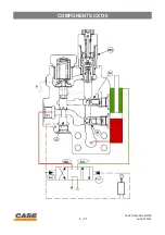
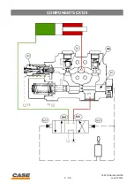
Страница 42: ...control for the solenoid valve is a button on the instrument panel The function of this cushion valve is to restrict the return of pilot oil from the control valve spool operated There is an other fun...

Страница 43: ...ONENTS CX130 3 9 CASE TRAINING CENTER AUGUST 2000 TANK CONTROL VALVE BOOM CONTROL VALVE DIPPER SOLENOID VALVE CUSHION VALVE FILTER PILOTE CUSHION BUTTON a b c d ARM CLOSED OPEN BOOM UP DOWN PRESSURE P...

Страница 44: ...oss drilled orifices of the spools E and the remote control valve The control valve spool stays in neutral position When the lever is neutral the heat oil separated from the oil cooler line enters the...

Страница 45: ...ING CENTER AUGUST 2000 Neutral position TO BOOM OR ARM SPOOL SPOOLS E FROM PILOT PRESSURE TO RETURN FILTER FROM HAND CONTROL S PORT FROM CONTROL VALVE RETURN CUSHION SHUT OFF SOLENOID VALVE TO RETURN...

Страница 46: ...sure goes freely to the control valve work spool end through D port The oil in the opposite end spool of the control valve return to the tank through the port C and the opened return filter port T Hea...

Страница 47: ...CENTER AUGUST 2000 Piloting TO BOOM OR ARM SPOOL TO RETURN FILTER SPOOL F SPOOLS E ORIFICE FROM PILOT PRESSURE CUSHION SHUT OFF TO RETURN FILTER FROM HAND CONTROL SOLENOID VALVE ORIFICE S PORT FROM CO...

Страница 48: ...to use The pressurized oil flow from port D is going to middle room first however due to the orifice restriction the oil flow is separated and such separated oil flow pushes up the spool to lower room...

Страница 49: ...0 Cushionning operation TO BOOM OR ARM SPOOL FROM CONTROL RETOUR DE FUITE TO RETURN FILTER CUSHION SHUT OFF SOLENOID VALVE ORIFICE S FROM PILOT PRESSURE SPOOL E SPOOL F CONTROLS ORIFICES ORIFICES FROM...

Страница 50: ...ds the signal to a solenoid valve Then from solenoid valve the original pressure 40K of pilot comes into the cushion valve from port S and the cushion spool inside the valve is switched The pressurize...

Страница 51: ...UGUST 2000 Cushion cancellation TO RETURN FILTER TIROIR E ORIFICE S PRESSION DE PILOTAGE TO HAND CONTROL FROM CONTROL TO RETURN FILTER CUSHION SHUT OFF SOLENOID VALVE FROM HAND CONTROL TO BOOM OR ARM...

Страница 52: ...000 psi 3 4 S Intake port SAE 2500 psi 2 1 2 T Drain port G 3 8 Pz1 z2 Negative flow control pressure port G 1 4 X3 G1 2 6 7 Gauge port G 1 4 G4 Gauge port G 3 8 X8 Gear pump discharge s G 3 8 S Gear...

Страница 53: ...COMPONENTS CX130 3 19 CASE TRAINING CENTER AUGUST 2000 Pump...

Страница 54: ...3 20 COMPONENTS CX130 CASE TRAINING CENTER AUGUST 2000 Pump follow...

Страница 55: ...COMPONENTS CX130 3 21 CASE TRAINING CENTER AUGUST 2000 Pump follow...

Страница 56: ...3 22 COMPONENTS CX130 CASE TRAINING CENTER AUGUST 2000 Pump control block follow...

Страница 57: ...COMPONENTS CX130 3 23 CASE TRAINING CENTER AUGUST 2000 Pump control block...

Страница 58: ...3 24 COMPONENTS CX130 CASE TRAINING CENTER AUGUST 2000 Pump rotating group assembly follow...

Страница 59: ...COMPONENTS CX130 3 25 CASE TRAINING CENTER AUGUST 2000 Pump rotating group assembly follow...

Страница 60: ...3 26 COMPONENTS CX130 CASE TRAINING CENTER AUGUST 2000 Pilot pressure pump...

Страница 61: ...COMPONENTS CX130 3 27 CASE TRAINING CENTER AUGUST 2000 Pilot pressure pump...

Страница 62: ...3 28 COMPONENTS CX130 CASE TRAINING CENTER AUGUST 2000 Proportional solenoid valve...

Страница 63: ...COMPONENTS CX130 3 29 CASE TRAINING CENTER AUGUST 2000 Proportional solenoid valve...

Страница 64: ...in line dr1 dr2 Dipper arm out 5A5 Arm anti drift PS2 Dipper arm in 5B5 Boom anti drift Right swing 5B2 Ultra clean filter supply R5 Left swing 5A2 Pilot circuit heating R4 Auxiliary 5A4 Swing priorit...

Страница 65: ...E TRAINING CENTER AUGUST 2000 Control valve MOUNTING THREAD MAIN RELIEF VALVE LEFT SIDE BOOM ANTIDRIFT ARM ANTI DRIFT ARM IN SWING PRIORITY RIGHT SIDE NEGATIVE FLOW CONTROL PRESSURE VALVE REGENERATION...

Страница 66: ...FT VALVE STRAIGHT TRAVEL SIGNAL SWITCH VALVE ORIFICE PLUNGER CHECK VALVE PORT RELIEF VALVE PLUG LOAD CHECK VALVES END PLATE PLUG PILOT POPPET PLUG ARM REGENERATION CHECK VALVE PLUG BOOM BACK PRESSURE...

Страница 67: ...ANTI DRIFT VALVE CHECK VALVES PLUNGER CHECK VALVE MAIN RELIEF VALVE O RING O RING O RING O RING O RING PILOT POPPET FITTING PLUG SPOOL COVER BOLT O RING PORT RELIEF VALVE NEGATIVE FLOW CONTROL PRESSUR...

Страница 68: ...3 34 COMPONENTS CX130 CASE TRAINING CENTER AUGUST 2000 Boom savety valve H B C V...

Страница 69: ...COMPONENTS CX130 3 35 CASE TRAINING CENTER AUGUST 2000 Dipper arm savety valve H B C V...

Страница 70: ...tank by 3C spool Boom up The remote control pressure 4b22 pushes the control valve spool The oil flows out of the control valve 4B2 port enters the safety valve P1 port pushes the 3B check valve and g...

Страница 71: ...COMPONENTS CX130 3 37 CASE TRAINING CENTER AUGUST 2000...

Страница 72: ...pushes the 3B check valve and goes to the cylinder rod end through the port P2 directly connected with the cylinder rod end The oil of the piston end goes to the return through the 5B5 port of the co...

Страница 73: ...COMPONENTS CX130 3 39 CASE TRAINING CENTER AUGUST 2000...

Страница 74: ...3 40 COMPONENTS CX130 CASE TRAINING CENTER AUGUST 2000 Dual flow valve...

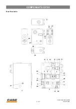
Страница 75: ...COMPONENTS CX130 3 41 CASE TRAINING CENTER AUGUST 2000 Dual flow valve...

Страница 76: ...3 42 COMPONENTS CX130 CASE TRAINING CENTER AUGUST 2000 Swing motor...

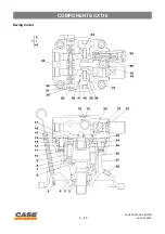
Страница 77: ...COMPONENTS CX130 3 43 CASE TRAINING CENTER AUGUST 2000 Swing motor...

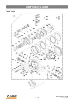
Страница 78: ...3 44 COMPONENTS CX130 CASE TRAINING CENTER AUGUST 2000 Travel motor...

Страница 79: ...COMPONENTS CX130 3 45 CASE TRAINING CENTER AUGUST 2000 Travel motor...

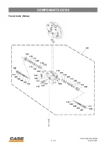
Страница 80: ...3 46 COMPONENTS CX130 CASE TRAINING CENTER AUGUST 2000 Travel motor follow...

Страница 81: ...COMPONENTS CX130 3 47 CASE TRAINING CENTER AUGUST 2000 Travel motor follow...

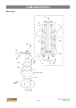
Страница 82: ...3 48 COMPONENTS CX130 CASE TRAINING CENTER AUGUST 2000 Swivel joint...

Страница 83: ...COMPONENTS CX130 3 49 CASE TRAINING CENTER AUGUST 2000 Swivel joint...

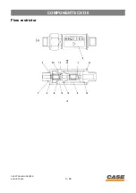
Страница 84: ...3 50 COMPONENTS CX130 CASE TRAINING CENTER AUGUST 2000 Flow restrictor...

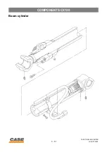
Страница 85: ...COMPONENTS CX130 3 51 CASE TRAINING CENTER AUGUST 2000 Boom cylinder...

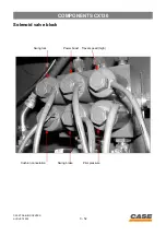
Страница 86: ...3 52 COMPONENTS CX130 CASE TRAINING CENTER AUGUST 2000 Solenoid valve block Travel speed high Swing brake Power boost Cushion cancelation Swing lock Pilot pressure...

Страница 87: ...HYDRAULIC EXCAVATOR CX130 CASE TRAINING CENTRE AUGUST 2000 SECTION N 4 DIAGNOSTIC MODEL SELECTION...

Страница 88: ...CENTRE DE FORMATION CASE EDITION AOUT 2000...

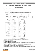
Страница 89: ...m press the travel speed switch To erase the data press the work mode switch for 10 seconds and the audible warning device sounds F To detect overloads on the electrical circuit press the travel speed...

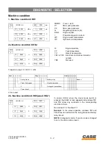
Страница 90: ...nged to zero the data is also erased CHK MODE II H ENG 2000 rpm 1 P1 030 0 MPa I 0300 mA P2 030 0 MPa WT 0080 C N 03 00 MPa OT 0055 C MODE Travel work P1 Main pump pressure P2 Main pump pressure N Reg...

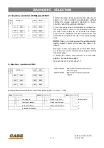
Страница 91: ...at means that there is no defect Example In the screen opposite window TR1 shows a short circuit at the travel second speed control transistor output 3 When the starter motor switch is in the OFF posi...

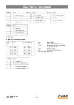
Страница 92: ...Engine idle Windshield wiper X SW7 0 0 0 0 Anti theft Starter motor switch Overload indicator X CHK MODE I H TG 0000 4 FS 0080 BP 0000 AC 0005 SP1 0000 TR5 0010 SP2 0000 FS Fuel gauge AC A C control...

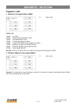
Страница 93: ...k position detector 0032 and in the fuel temperature sender 0016 DIAG MODE II H E 0000 1 E 0015 E 0000 E 0000 E 0000 E 0000 E 0000 E Failure code E0000 No defect E0015 Engine water temperature sender...

Страница 94: ...reens DIAG2 and DIAG3 it is recorded in the electronic control box memory this data is only visible using an external computer 4 Excavator failure detection DIAG4 Failure code Example The screen above...

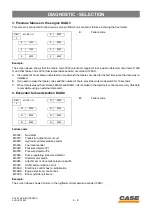
Страница 95: ...il temperature sender occurred at 1200 H and that failure code 0030 occurred at 1000 H A The numbers of hours shown indicate the time at which the failures occurred for the first time since the data w...

Страница 96: ...Length of time excavator was used in H S Length of time excavator was used in S L Length of time excavator was used in L A Length of time excavator was used in AUTO WT Maximum engine temperature OT Hy...

Страница 97: ...30 MPa and 350 bar 35 MPa 7 350 bar 35 MPa or above HR MODE II H 4 0000 6 1 0000 5 0000 2 0000 6 0000 3 0000 7 0000 1 1200 rpm or lower 2 Between 1200 rpm and 1400 rpm 3 Between 1400 rpm and 1600 rpm...

Страница 98: ...itch for 10 seconds or more HR MODE II H 4 0000 9 1 0000 5 0000 2 0000 6 0000 3 0000 7 0000 1 30 C or lower 2 30 C to 40 C 3 40 C to 50 C 4 50 C to 60 C 5 60 C to 70 C 6 70 C to 80 C 7 80 C or higher...

Страница 99: ...seconds The audible warning device sounds when saving is completed D Turn the starter key switch to the OFF position E Check the engine speed on screen CHK1 Example In the above screen the engine spe...

Страница 100: ...the selection press the work mode switch for 10 seconds The audible warning device sounds when saving is completed D Turn the starter key switch to the OFF position Example In the above screen the typ...

Страница 101: ...n the following order 0000 0001 0010 0011 0100 0101 up to 1100 1101 1110 1111 0000 C To save the settings press the work mode switch for 10 seconds The audible warning device sounds when saving is com...

Страница 102: ...rvice interval is due The message is displayed five times when the engine is started up LOW FUEL Yes This message shows that the level of fuel in the fuel tank is low and that more fuel should be adde...

Страница 103: ...DIAGNOSTIC SELECTION 4 15 CASE TRAINING CENTER AUGUST 2000...

Страница 104: ...s the travel mode switch to display the required language 0 Japanese 1 English 2 Thai 3 Chinese 4 German 5 French 6 Italian 7 Spanish 8 Portuguese 9 Dutch 10 Danish 11 Norwegian 12 Swedish 13 Finnish...

Страница 105: ...from the beginning If the engine electronic control box installed is not correct change it 10 To confirm the excavator model selection press the auto mode switch for 10 seconds The screen below will...

Страница 106: ...seconds To change the language code press the travel mode switch to display the required code To confirm the language code press the work mode switch and the audible warning device sounds Turn the sta...

Страница 107: ...t be changed without consult ing your CASE Dealer Entering the code Step 1 Place the starter switch key in ON position Step 2 he message Password and four boxes will appear on the display screen Step...

Страница 108: ...to activate the anti theft device If you so wish when shutting down the engine simply place the starter switch key in the OFF position and it will not be necessary to enter the access code to start t...

Страница 109: ...male plug C Radio connector 1 Remove the hood A located behind the operator s seat 2 Disconnect the two wires A B covering the anti theft system 3 Turn the starter key switch to ON and then OFF 4 Rec...

Страница 110: ...starter motor terminals and wiring for tightness and corrosion Tighten or change Tighten or change Tighten or change OTHER POINTS TO CHECK Hydraulic system Mechanical equipment 12 Abnormal noise or sm...

Страница 111: ...situation NO if they do not meet it The necessary preparation work operating method and the criteria are described under one step This should be carefully read before starting the inspection and the...

Страница 112: ...even after refilling the fuel tank 1 Low coolant The message is still displayed even after refilling with coolant solution 2 Low oil press The message is still displayed even after adjusting the engi...

Страница 113: ...Refer to the table below for the resistance NO Defective fuel level sender Change or check the fuel level sender YES Disconnect the CN24 connector to measure the resistance between GL female and the G...

Страница 114: ...k level pressure switch connector to see if the message disappears YES Reserve tank level pressure switch is defective Change the reserve tank NO Disconnect connector CN24 to see if the message disapp...

Страница 115: ...e 12 seconds following starting the engine Disconnect the oil pressure switch connector to see if the message disappears YES Oil pressure switch defective Change NO Disconnect connector CN24 to see if...

Страница 116: ...is less than the following Hydraulic oil temperature 84 C engine coolant temperature 92 C Prior check 1 Make sure that 8 bars are displayed on the hydraulic oil and engine coolant temperature gauge b...

Страница 117: ...e the resistance NO Coolant temperature sender defective Change the temperature sender YES Disconnect connectors CN24 and CNAO to measure the resistance between the female terminals PL and BP Refer to...

Страница 118: ...ance Refer to the table below for the resistances NO Temperatur e sender oil defective Change the oil temperature sender YES Disconnect connector CN24 to measure the resistance between the male termin...

Страница 119: ...s NOTE The resistance varies with the temperature Coolant or oil temperature Coolant temperature detector Oil temperature detector 20 C 6 08 k9 2 45 k9 30 C 4 24 k9 1 66 k9 40 C 3 02 k9 1 15 k9 50 C 2...

Страница 120: ...ENTER AUGUST 2000 Battery charge circuit defective Description of problem No 5 The message is still displayed CM00F005 1 Main electronic control box 2 Hourmeter 3 Battery relay 4 Alternator 5 Starter...

Страница 121: ...e alternator or defective alternator Repair wire BrR543 or change the alternator Disconnect CN1 to measure the voltage between wire BrR543 at the main electronic control box end and earth Over 10 V YE...

Страница 122: ...m troubleshooting Description of problem No 6 The message is still displayed CS00F528 1 Main electronic control box 2 Engine electronic control box 3 Engine 4 Electronic regulator 5 Engine speed detec...

Страница 123: ...AINING CENTER AUGUST 2000 8 Fuse 9 Shock absorbing solenoid valve 10 Swing cancellation solenoid valve 11 Function locking solenoid valve 12 Swing brake solenoid valve 13 Travel 2nd speed solenoid val...

Страница 124: ...circuited YES To CHK2 Self detection finds the short circuit YES The failure code disappears after disconnecting the solenoid valve connector YES Defective solenoid valve Change the solenoid valve NO...

Страница 125: ...ayed Prior checks 1 Make sure there are no problems with the engine and in the fuel system 2 Make sure that the fuses are intact 3 Make sure that the starter motor is working and turning the engine CM...

Страница 126: ...or connector and CN or on wire LR between the fuse and CN Repair the wire LR YES Using the same configuration check for continuity between wires L and LW Starting motor switch ON continuity Starting m...

Страница 127: ...e solenoid valve and the hydraulic system see hydraulic system troubleshooting The voltage is below 24 V at the output from the electronic control box CN6 borne 30 Change the harness 3 Using diagnosti...

Страница 128: ...n the CHK1 check screen The electrical harness between the hydraulic oil temperature sender and the electronic control box CN1 terminal 6 and 13 is defective Repair the electrical harness Voltage belo...

Страница 129: ...ails of service connector kit BS98F224 1 For engine emergency stop motor 6P BS98F225 2 For harness end of engine emergency stop motor 6P BS98F226 3 For solenoid valve and fuel gauge BS98F527 4 For pro...

Страница 130: ...42 DIAGNOSTIC SELECTION CASE TRAINING CENTER AUGUST 2000 CS00E531 8 For hydraulic oil temperature and engine coolant temp senders CS00E530 9 For engine speed detector CS00E532 10 For pressure detecto...

Страница 131: ...onnector at the main harness end and install the meter NOTE The terminal of the meter should be connected to wire BrB brown black on the service connector coming from the main harness and the terminal...

Страница 132: ...ervice connector 6P to the connector at the main harness end only 3 Make sure that wire LR blue red on the service connector is connected to wire LR on the main harness and install the meter NOTE The...

Страница 133: ...1 Disconnect connector A from one of the solenoids on the 6 solenoid valve block B CD00F023 Marking Function Ring colour 1 Swing pilot cancellation Green 2 Power boost Yellow 3 2nd travel speed Red 4...

Страница 134: ...843 2 Connect the appropriate service connector 2P to the connector on the disconnected solenoid only and install the meter 3 When the connection has been made the solenoid resistance reading should b...

Страница 135: ...DIAGNOSTIC SELECTION 4 47 CASE TRAINING CENTER AUGUST 2000 Engine speed detector CX130 CD00F024 CX210 CD00F025 1 Disconnect connector A from the engine speed detector A A...

Страница 136: ...98F255 2 Connect the appropriate service connector 2P to the connector on the speed detector only and install the meter 3 When the connection has been made the speed detector resistance should be 0 7...

Страница 137: ...SELECTION 4 49 CASE TRAINING CENTER AUGUST 2000 Engine coolant and hydraulic oil temperature senders CX130 CD00F026 CX210 CD00F027 CX130 CX210 CD00F028 A Coolant temperature sender B Oil temperature s...

Страница 138: ...e service connector 2P to the temperature sender and install the meter 3 When the connection has been made place the sender in the beaker and gradually increase the temperature in the beaker using the...

Страница 139: ...NG CENTER AUGUST 2000 Pressure sender CX130 CD00E145 CX210 CD00E146 P1 Pressure detector P1 P2 Pressure detector P2 N Pump regulating pressure detector 1 Disconnect the pressure detector connector fro...

Страница 140: ...E The terminal on the meter should be connected to wire YL yellow blue on the service connector and the terminal to the machine earth 3 When the connection has been made start the engine and check the...

Страница 141: ...HYDRAULIC EXCAVATOR CX130 CASE TRAINING CENTRE AUGUST 2000 SECTION N 5 ELECTRICAL...

Страница 142: ...CENTRE DE FORMATION CASE EDITION AOUT 2000...

Страница 143: ...CENTRE DE FORMATION CASE EDITION AOUT 2000...

Страница 144: ...CIRCUIT CASE TRAINING CENTER AUGUST 2000 General location of components outside the cab Model CX130 CM00E003 1 2 3 4 5 6 7 8 9 10 11 12 13 14 15 16 17 18 19 20 21 22 23 25 24 26 27 28 29 34 33 32 31 3...

Страница 145: ...raulic pump regulating pressure detector 19 P2 pressure detector yellow ring 20 P1 pressure detector 21 Hydraulic oil temperature sender 22 Starter motor 23 Electronic regulator 24 Fuel flow regulatin...

Страница 146: ...5 3 ELECTRIC CIRCUIT CASE TRAINING CENTER AUGUST 2000 Model CX210 CM00E004 1 2 3 4 5 6 8 9 10 11 7 13 14 16 17 19 15 21 18 22 23 25 24 26 27 28 29 34 33 32 31 30 35 36 37 38 12 20...

Страница 147: ...draulic pump regulating pressure detector 19 P2 pressure detector yellow ring 20 P1 pressure detector 21 Hydraulic oil temperature sender 22 Starter motor 23 Electronic regulator 24 Fuel flow regulati...

Страница 148: ...5 5 ELECTRIC CIRCUIT CASE TRAINING CENTER AUGUST 2000 Relays and main fuses battery compartment Model CX130 CI00E501 6 5 1 2 3 4...

Страница 149: ...el CX210 CI00E502 1 Battery relay 2 Fuse 65A protection of circuits F3 to F10 and F13 to F20A 3 Fuse 20A protection of circuits F11 and F12 before contact 4 Fuse 20A protection of circuits F1 5 Fuse 2...

Страница 150: ...5 7 ELECTRIC CIRCUIT CASE TRAINING CENTER AUGUST 2000 General location of components inside the cab CM00E002 1 2 3 4 5 6 7 8 9 10 11 12 13 14 15 16 17 18 27 19 20 21 22 23 24 26 25...

Страница 151: ...nic control box 10 Rotary light relay 11 Engine emergency stop relay 12 Working lights relay 13 Horn relay 14 Pre heat plug relay 15 DC DC converter 24 V 12 V 16 Solar radiation detector 17 Radio 18 C...

Страница 152: ...10A Rotary light F7 Fuse 20A Fuel filler pump F8 Fuse 15A Engine emergency stop motor F9 Fuse 30A Pre heater plug F10 Fuse 10A Option F11 Fuse 10A Memory F12 Fuse 10A Starting radio and cab light swi...

Страница 153: ...stop switch 7 Hourmeter 8 Shock absorption Hard soft switch 9 Rotary light switch 10 Working light switch 11 Windshield wiper switch 12 Windshield washer switch 13 Control screen CS00F521 14 Travel s...

Страница 154: ...Engine electronic control box 7 Electronic acceleration 8 Engine speed detector 9 Fuel flow regulating resistor 10 Engine water temperature sender 11 Fuel temperature sender 12 Engine 13 Rack detector...

Страница 155: ...ntrol box 2 The engine electronic control box determines the fuel injection flow This flow is determined from the water temperature data and the real number of revolutions of the engine 3 Once the sta...

Страница 156: ...Working mode switch 2 Automatic mode switch 3 Instrument panel 4 Main electronic control box 5 Proportioning valve 6 Engine electronic control box 7 Electronic acceleration 8 Engine 9 SERIES communic...

Страница 157: ...onic control box 4 which changes the mode in accordance with the input signal 2 The electronic control box 4 transmits the selected mode to the control screen LCD via series communications 9 The contr...

Страница 158: ...raulic hammer or grab is used the pump is controlled by the value of S mode current 4 If the engine coolant solution temperature is too low or the voltage arriving at the engine electronic control box...

Страница 159: ...perature is below 50 C or the oil temperature below 25 C auto mode control does not operate and LA mode is selected When the water temperature is above 50 C and the oil temperature above 25 C auto mod...

Страница 160: ...the rack using the target number of revolutions and the data from each detector real number of engine revolutions real position of the rack fuel flow regulating resistance and it sends the signal to...

Страница 161: ...CASE TRAINING CENTER AUGUST 2000 3 Relation between the throttle control and the number of engine revolutions 0 100 5 0 Input voltage Volt Throttle control 0 100 NH Speed rpm Throttle control NS NL NI...

Страница 162: ...turn to idle OFF manual return to idle by pressing the return to idle control button 2 When the machine is started up it will be in the previous return to idle mode 3 If no function is operated and id...

Страница 163: ...the engine speed drops to the pre set hammer speed see engine speed setting for hammer option When the option pedal returns to the neutral position the hammer pressure switch 2 is deactivated and the...

Страница 164: ...n for 2 seconds more 4 When the ignition switch is turned 3 to START ST IN2 ON the engine electronic control box 4 reactivates the pre heat relay 5 but does not transmit a signal to the main electroni...

Страница 165: ...ng pre heating time Tp and after pre heat Ta 10 5 0 5 10 15 20 0 2 4 6 8 10 12 14 16 Pre heating time Tp in seconds Engine coolant solution temperature C 10 5 0 5 10 15 20 0 10 20 30 40 50 60 70 80 Ti...

Страница 166: ...Water temp Calculated time Glow plug on Elapsed time Glow plug activated for Glow plug deactivated Signal deactivated Signal active Time calculation pre heat Glow plug on Engine started Time calculat...

Страница 167: ...G PRE HEAT is displayed A Pre heating time Tp B 2 seconds of additional pre heat C Pre heating time when engine is being started D Time after pre heat Ta OFF ON OFF ST ON OFF Control screen Pre heat C...

Страница 168: ...matic engine warm up signal to the engine electronic control box 7 2 The engine electronic control box 7 manages the automatic engine warm up 3 Automatic engine warm up conditions Coolant solution tem...

Страница 169: ...CENTER AUGUST 2000 3 Diagram showing times 1200 1500 1800 5 3 3 3 Engine speed rpm Floating engine throttle control Warm up time in minutes 1200 1500 1800 Engine speed rpm 5 3 3 Floating engine throt...

Страница 170: ...control box 2 Engine 3 Engine coolant temperature sender 4 Electronic acceleration 2 Operation When the idle time is too long and the voltage supplied to the engine electronic control box 1 drops or...

Страница 171: ...GUST 2000 Adjusting the idle speed in accordance with the coolant solution temperature NOTE Numbers in brackets show values for the CX130 30 15 10 20 700 800 800 900 900 1000 1000 1100 1100 1200 1200...

Страница 172: ...t 0 volt the emergency stop relay 3 is activated along with the emergency stop motor 5 3 The stop signal input IN1 on the engine electronic control box 4 falls to 0 volt the engine electronic control...

Страница 173: ...RIC CIRCUIT 5 30 CASE TRAINING CENTER AUGUST 2000 3 Timing diagram 24 V 0 V ON OFF ON OFF ON OFF NO NC ON OFF ON OFF Supply OUT1 IN1 LED OUT2 Emergency stop switch Emergency stop relay Emergency stop...

Страница 174: ...ue of the rack position is then transmitted to the engine electronic control box The engine electronic control box checks if the electronic acceleration regulator is operating correctly by comparing t...

Страница 175: ...Engine control when the emergency mode has taken over The engine electronic control box determines the target engine speed from the position of the engine throttle control The engine electronic contro...

Страница 176: ...ming diagram 3 Operation When the engine is started and the control cancellation lever is in the work position the pilot pressure solenoid valve is activated When the pilot pressure solenoid valve is...

Страница 177: ...by the engine electronic control box 6 The load on the hydraulic system transmitted by the pressure detectors P1 P2 2 and 3 If pressure P1 or P2 is higher than 300 bar 30 MPa and the load ratio remain...

Страница 178: ...2 10 Swing brake 11 Swing brake solenoid valve 2 Swing brake control operation When the swing brake switch 2 is operated the red LED comes on and the swing brake locks When the swing brake switch is o...

Страница 179: ...deactivated when The swing pilot pressure switch 5 is activated When the pressure at the pressure detectors P1 8 or P2 9 is higher than 150 bar 15 MPa The swing brake is automatically activated when...

Страница 180: ...l 2 Travel speed switch 3 Main electronic control box 4 Pressure detector P1 5 Pressure detector P2 6 Pump regulating pressure detector N 7 Travel pilot pressure switch 8 Travel 2nd speed solenoid val...

Страница 181: ...pressure P1 or P2 is lower than 40 bar 4 MPa at the electronic control box output OUT the travel change speed solenoid valve is deactivated 1st speed 2 When pressure P1 or P2 is higher than 40 bar 4...

Страница 182: ...pressure switch ON Travel mode Hyd temp 25 P1 50 bar P2 50 bar PN 7 bar Actuel RPM target RPM P1 40 bar P2 40 bar Solenoid activated P1 30 bar P2 30 bar solenoid desactivated Yes No On Off 2 sec 2 sec...

Страница 183: ...3 Main electronic control box 4 Main fuses 5 Fuse box 6 Starter motor switch 7 Engine 8 Alternator 2 Timing diagram 3 1 2 4 5 6 8 7 0 5 sec 0 5 sec 3 sec 3 sec ON OFF 24 V 0 V 24 V 0 V ON 24 V OFF 0 V...

Страница 184: ...the electrical supply and the message ELEC PROBLEM appears on the instrument panel control screen Use the diagnostic mode to locate the short circuit Check the wiring and the components of the affecte...

Страница 185: ...control box 3 send the converted signal to the main electronic control box 2 via the CAN connection 8 C The main electronic control box 2 calculates the number of bars to display and transmits the in...

Страница 186: ...in electronic control box 2 B The main electronic control box 2 calculates the number of bars to be displayed and sends the information to the oil temperature gauge 4 via the series connection 5 C Whe...

Страница 187: ...the series connection 5 C When only one bar is displayed on the fuel level gauge 4 the message LOW FUEL appears on the instrument panel control screen 1 and the audible warning device sounds Remainin...

Страница 188: ...ol box 4 Main electronic control box 5 Fuel injection pump 6 Fuel flow regulating resistor 7 Electronic regulator 8 Engine speed detector 9 Throttle control 10 Starter motor switch 11 CAN connection 1...

Страница 189: ...n electronic control box 4 via the CAN connection 11 B The electronic regulator 7 has an input section a calculating section and a linear motor control section 17 C The input section receives the sign...

Страница 190: ......

Страница 191: ...HYDRAULIC EXCAVATOR CX130 CASE TRAINING CENTRE AUGUST 2000 SECTION N 6 HYDRAULIC CIRCUIT...

Страница 192: ...CENTRE DE FORMATION CASE EDITION AOUT 2000...

Страница 193: ...CENTRE DE FORMATION CASE EDITION AOUT 2000...

Страница 194: ...f control valve entry Each flow goes into the travel motor through the changing over of the left and right travel spool By these flows the machine travels forward and backward Electronic signals are s...

Страница 195: ...ON G ARRIERE AVANT R4 R5 4b4 4a42 4a41 4b3 4a3 4A2 4B2 4A3 4B3 4b22 4a2 4b21 4A1 4B1 4b1 4a1 P13 B 3 Ps2 0 29 Mpa 42 psi 2 9 bar PR A ROUGE SURTARAGE BLEU COMMANDE PRESSION PILOTAGE JAUNE 2eme VITESSE...

Страница 196: ...to Low Speed Discharged oil from A1 enters into the PR port of control valve entry while discharged oil from A2 enters into the PL port of control valve entry Each flow goes into the travel motor thr...

Страница 197: ...ON G ARRIERE AVANT R4 R5 4b4 4a42 4a41 4b3 4a3 4A2 4B2 4A3 4B3 4b22 4a2 4b21 4A1 4B1 4b1 4a1 P13 B 3 Ps2 0 29 Mpa 42 psi 2 9 bar PR A ROUGE SURTARAGE BLEU COMMANDE PRESSION PILOTAGE JAUNE 2eme VITESSE...

Страница 198: ...n find no place to go and the circuit pressure raises up to the original pressure 3 9 MPa This original pressure acts on the pilot chamber of the straight travel valve and the straight travel valve ch...

Страница 199: ...TRANSLATION G MONTEE DESCENTE ARRIERE AVANT R4 R5 4b4 4a42 4a41 4b3 4a3 4A2 4B2 4A3 4B3 4b22 4a2 4b21 4A1 4B1 4b1 4a1 P13 B 3 Ps2 0 29 Mpa 42 psi 2 9 bar PR A A C E F D B ARRIERE GAUCHE AVANT GAUCHE A...

Страница 200: ...ller and at the time when either one reaches 14 7 MPa the output to swing brake solenoid valve from the controller is turned OFF and the swing parking brake is released In 5 seconds after the swing pr...

Страница 201: ...Px2 Px1 Ps1 4b4 4a42 4a41 4b3 4a3 4A2 4B2 4A3 4B3 4b22 4a2 4b21 4A1 4B1 4b1 4a1 P13 B 10 P2 P0 P P3 P1 0 098 MPa 13 psi 0 9 bar 0 049 MPa 5 8 psi 0 4 bar 3 P12 P11 dr2 Ps2 0 29 Mpa 42 psi 2 9 bar ROUG...

Страница 202: ...are operated at the same time Additionally when trenching boom up pilot pressure is supplied from Pi1 port and the supply of hydraulic oil to the arm 1 is secured through moving the swing variable th...

Страница 203: ...5a52 5b52 5b51 5B4 5A4 5a4 5b4 OPT 5a31 5a32 5b31 5b32 5B2 5A2 5a2 5b2 2 5 2 5 5B1 5A1 5a1 5b1 Px2 Px1 Ps1 P12 P11 dr2 a PY FR R2 GODET BALANCIER 2 OUVERT FERME PO FLECHE 1 TRANSLATION G MONTEE DESCEN...

Страница 204: ...2 Speed Circuit The discharged oil from A1 flows into the boom 1 spool via straight travel valve and left travel spool The discharged oil from A2 is supplied to the boom 2 spool from the parallel oil...

Страница 205: ...A5 5a52 5b52 5b51 5B4 5A4 5a4 5b4 OPT 5a31 5a32 5b31 5b32 5B2 5A2 5a2 5b2 2 5 2 5 5B1 5A1 5a1 5b1 Px2 Px1 Ps1 P12 P11 dr2 MONTEE DESCENTE a PY FR R2 PO FLECHE 1 MONTEE DESCENTE R4 R5 4b4 4a42 4a41 4b3...

Страница 206: ...nk line the rod of the boom cylinder shrinks and the boom is lowered Boom Down Recycle Circuit When boom down is operated pilot pressure is supplied at 4a2 and boom 1 spool is changed over The boom lo...

Страница 207: ...LIC CIRCUIT 6 14 CASE TRAINING CENTER AUGUST 2000 a PY FR R2 PO MONTEE R4 R5 4b4 4a42 4a41 4b3 4a3 4A2 4B2 4A3 4B3 4b22 4a2 4b21 4A1 4B1 4b1 4a1 P13 B 3 Ps2 0 29 Mpa 42 psi 2 9 bar PR A c FLECHE 1 DES...

Страница 208: ...l via the central bypass oil passage The discharge oil from A1 is supplied to the arm 2 spool through the central bypass oil passage via the straight travel valve and merges at the downstream of the a...

Страница 209: ...2 SORTIE BALANCIER 1 RENTREE PO SORTIE RENTREE R1 R4 R3 R5 5A5 5a52 5b52 5b51 5B4 5A4 5a4 5b4 OPT 5a31 5a32 5b31 5b32 5B2 5A2 5a2 5b2 2 5 2 5 5B1 5A1 5a1 5b1 Px2 Px1 Ps1 4b4 4a42 4a41 4b3 4a3 4A2 4B2...

Страница 210: ...nk line via the load holding valve poppet The pressure in the spring chamber of the load holding valve check decreases and the check is released The hydraulic oil at the rod of the arm cylinder is ret...

Страница 211: ...2 RENTREE SORTIE BALANCIER 1 PO SORTIE RENTREE R1 R4 R3 R5 5A5 5a52 5b52 5b51 5B4 5A4 5a4 5b4 OPT 5a31 5a32 5b31 5b32 5B2 5A2 5a2 5b2 2 5 2 5 5B1 5A1 5a1 5b1 Px2 Px1 Ps1 4b4 4a42 4a41 4b3 4a3 4A2 4B2...

Страница 212: ...valve and a port of the central bypass cut valve in the control valve The central bypass cut valve moves to the left and the central bypass is shut off Due to the pilot pressure entered P port of the...

Страница 213: ...5A4 5a4 5b4 OPT 5a31 5a32 5b31 5b32 5B2 5A2 5a2 5b2 2 5 2 5 5B1 5A1 5a1 5b1 Px2 Px1 Ps1 P12 P11 dr2 a PY FR R2 GODET BALANCIER 2 OUVERT FERME PO FLECHE 1 TRANSLATION G MONTEE DESCENTE ARRIERE AVANT S...

Страница 214: ...6 21 HYDRAULIC CIRCUIT CASE TRAINING CENTER AUGUST 2000 Circuit for Breaker Crusher Auxiliary Line Holding Valve HOLDING VALVE RELEASE SPOOL HOLDING VALVE P A B T T B P A CIRCUIT DIAGRAM...

Страница 215: ...HYDRAULIC CIRCUIT 6 22 CASE TRAINING CENTER AUGUST 2000...

Страница 216: ...ds the breaker side and the pedal is stepped forward pilot pressure is detected by the pressure switch then the engine falls to the preset revolution by the controller The pilot pressure entered at 5a...

Страница 217: ...5a4 5b4 OPT 5a31 5a32 5b31 5b32 5B2 5A2 5a2 5b2 2 5 2 5 5B1 5A1 5a1 5b1 Px2 Px1 Ps1 P12 P11 dr2 a PY FR R2 GODET BALANCIER 2 OUVERT FERME PO FLECHE 1 TRANSLATION G MONTEE DESCENTE ARRIERE AVANT SORTIE...

Страница 218: ...6 25 HYDRAULIC CIRCUIT CASE TRAINING CENTER AUGUST 2000 OPTION CIRCUITS Hammer option Double acting option...

Страница 219: ...HYDRAULIC CIRCUIT 6 26 CASE TRAINING CENTER AUGUST 2000 Clamshell option Multipurpose option...

Страница 220: ...6 27 HYDRAULIC CIRCUIT CASE TRAINING CENTER AUGUST 2000 2nd auxiliary circuit option Hammer and 2nd auxiliary option...

Страница 221: ...HYDRAULIC CIRCUIT 6 28 CASE TRAINING CENTER AUGUST 2000 Clamshell and 2nd auxiliary option Clamshell and double acting option...

Страница 222: ...6 29 HYDRAULIC CIRCUIT CASE TRAINING CENTER AUGUST 2000 Clamshell and 2nd auxiliary and multipurpose option...

Страница 223: ...HYDRAULIC CIRCUIT 6 30 CASE TRAINING CENTER AUGUST 2000 PUMP CX 130 Pump engine stopped...

Страница 224: ...S diameter area S and S S S D D Torque regulation spool used to limit mechanically the torque of the pump E E Negative flow control valve used to limit the pump flow according the operator demand F Pr...

Страница 225: ...C CIRCUIT 6 32 CASE TRAINING CENTER AUGUST 2000 3 92 Mpa 565 psi 39 bar M ISUZU 4BGIT 66 2KW 2100 G1 A1 G2 A2 G3 X3 A3 G4 G5 G6 G7 T2 T1 R2 R1 PZ2 T X7 X8 X1 PZ1 S S3 X4 X2 FL FR R2 3 0 29 Mpa 42 psi...

Страница 226: ...orifice PZ1 and PZ2 and fully push the Nega tive flow control valve E to the left The B B pistons of the servo pistons are connected with A A piston but the force is higher on B B pis ton bigger area...

Страница 227: ...C CIRCUIT 6 34 CASE TRAINING CENTER AUGUST 2000 3 92 Mpa 565 psi 39 bar M ISUZU 4BGIT 66 2KW 2100 G1 A1 G2 A2 G3 X3 A3 G4 G5 G6 G7 T2 T1 R2 R1 PZ2 T X7 X8 X1 PZ1 S S3 X4 X2 FL FR R2 3 0 29 Mpa 42 psi...

Страница 228: ...delivery flow is maximum If the operator reduces the flow demand the Negative flow control pressure signal increases the valve E comes back to the right and the piston B receives pressure from the val...

Страница 229: ...C CIRCUIT 6 36 CASE TRAINING CENTER AUGUST 2000 3 92 Mpa 565 psi 39 bar M ISUZU 4BGIT 66 2KW 2100 G1 A1 G2 A2 G3 X3 A3 G4 G5 G6 G7 T2 T1 R2 R1 PZ2 T X7 X8 X1 PZ1 S S3 X4 X2 FL FR R2 3 0 29 Mpa 42 psi...

Страница 230: ...through E E valves The two pumps deliver the same maximum flow A difference of pressure between the RH and LH side doesn t affect the outputs because the pistons A A receives the same pressure from t...

Страница 231: ...C CIRCUIT 6 38 CASE TRAINING CENTER AUGUST 2000 3 92 Mpa 565 psi 39 bar M ISUZU 4BGIT 66 2KW 2100 G1 A1 G2 A2 G3 X3 A3 G4 G5 G6 G7 T2 T1 R2 R1 PZ2 T X7 X8 X1 PZ1 S S3 X4 X2 FL FR R2 3 0 29 Mpa 42 psi...

Страница 232: ...e on the levers L L coming from the compensation valve C is required to press onto the adjustable spring of the torque regulation valve D D to reduce the swash plate angles 1 In H mode the proportiona...

Страница 233: ...C CIRCUIT 6 40 CASE TRAINING CENTER AUGUST 2000 3 92 Mpa 565 psi 39 bar M ISUZU 4BGIT 66 2KW 2100 G1 A1 G2 A2 G3 X3 A3 G4 G5 G6 G7 T2 T1 R2 R1 PZ2 T X7 X8 X1 PZ1 S S3 X4 X2 FL FR R2 3 0 29 Mpa 42 psi...

Страница 234: ......

Страница 235: ...HYDRAULIC EXCAVATOR CX130 CASE TRAINING CENTRE AUGUST 2000 SECTION N 7 SETTINGS...

Страница 236: ...CENTRE DE FORMATION CASE EDITION AOUT 2000...

Страница 237: ...valves boom dipper and bucket 383 5 bar Secondary relief valves swing 279 4 bar Safety valves boom and dipper 383 5 bar Upperstructure swing Type of motorfixed flow axial piston type Displacement 65...

Страница 238: ...rs 0 600 bar V5344460 2 straight unions for detector W5344461 1 elbow union for detector X5344462 1 engine speed detector Z5344463 3 cables 5 m long E3144472 1 electric plug 220V50Hz D5344467 1 cigare...

Страница 239: ...Main pump intake SAE 6000 psi 3 4 S3 Pilot pump intake G 3 4 T Return from pilot circuit secondary relief valve G 3 8 PZ1 PZ2 Pump pressure regulation P1 P2 G 1 4 X3 Regulating pressure detector G 1 4...

Страница 240: ...LIC PRESSURE SETTINGS CASE TRAINING CENTER AUGUST 2000 CX130 control valve CI00E504 CI00E505 dr1 P11 dr2 P12 5A5 5A2 5A1 OPT 5B5 5B4 5B2 5B1 PS1 P2 PX2 PX1 FL FR CI00E506 4B1 4B2 4B3 R5 R4 PI3 4A3 4A2...

Страница 241: ...rward travel 5B1 RH reverse travel G 3 4 PR PL Inlet pump P1 P2 G 3 4 P0 OPT Supply to option spool G 1 2 R1 R3 Plugged R2 Check valve return 2 9 bar FL FR Pump regulating pressure N PX1 Attachment an...

Страница 242: ...fold CD00E143 Port Description B Supply to pilot manifold T Return to reservoir C1 Select 2nd travel speed C2 Swing brake control C3 Higher pressure 2 stage relief C4 Cancel pilot system shock absorbi...

Страница 243: ...n Release pressure in the circuits completely before disconnecting pipes or carrying out any operation on the hydraulic system Always use a small piece of cardboard or wood to detect leaks of fluid un...

Страница 244: ...S mode on the diagnostic screen that the following values are respected Lower the engine speed to idle for 30 seconds then shut down the engine Turn the starter key switch to ON without starting the...

Страница 245: ...hydraulic pump flows CX130 CD00F008 Remove the hose 1 de the pump outlet to be checked Install the flange 2 CAS 2764 on the hose 1 Connect the elbow union 3 CAS 2764 on the pump outlet to be checked I...

Страница 246: ...up the engine 1 Start the engine The engine will have warmed up in 10 15 minutes 2 Run the engine until the message Automatic pre heating disappears from the display monitor 6 Warming up the hydrauli...

Страница 247: ...C Boom lowering secondary relief valve 196 bar 19 6 MPa 212 bar 21 2 MPa D Dipper extending secondary relief valve 196 bar 19 6 MPa 212 bar 21 2 MPa E Dipper retracting secondary relief valve 196 bar...

Страница 248: ...ment 1 Loosen the lock nut and turn the valve adjusting screw H until 39 1 bar 3 9 0 1 MPa is reached 2 Tighten the lock nut while holding the adjusting screw in position 3 When the adjusting screw ha...

Страница 249: ...ssure NOTE To read the higher pressure 2 stage relief level again the control lever should be released then operated against the cylinder stops Adjusting the higher pressure 2 stage relief CX130 CS00E...

Страница 250: ...hile holding the adjusting screw 3 in position 3 When the adjusting screw has been tightened check the pressure again and make sure there are no leaks Attachment secondary relief valves B C D E F and...

Страница 251: ...tic screen CHK1 3 Start the engine and select the S mode 4 Operate the swing brake control on the instrument panel indicator lamp ON 5 Slowly operate the swing lever to the right then gradually increa...

Страница 252: ...7 of the valve and tighten the plug 1 to 157 Nm 5 Reassemble the valve on the swing motor and the tighten to 78 Nm 6 Check the pressure of the valves again and make sure there are no leaks Checking t...

Страница 253: ...lect mode S Checking for leaks on the travel motor Tools required CS99B579 1 locking pin of above dimensions 1 receptacle of10 litres capacity 1 hose 1 plug Checking for leaks With the hydraulic oil b...

Страница 254: ...plug Checking for leaks With the hydraulic oil between 45 and 55 C 1 Disconnect the swing solenoid valve connector green 2 Display the diagnostic screen CHK1 3 Start the engine and select the mode S 4...

Страница 255: ...Pa Check the main valve Adjust or change Check the pump regulator or body which is at fault Adjust or change Pressure below 6 bars 0 6 MPa Check the travel spool pilot pressure on the side which is at...

Страница 256: ...the pump regulating pressure N Too high Adjust the pressure 4 Check the pilot pressure at the output from solenoid valve C1 Pressure too low Check the electrical supply and the solenoid valve coil No...

Страница 257: ...swing Check or change the swing cancellation solenoid valve The swing operates normally Check the solenoid valve supply electrical circuit 5 With the engine at full speed and hydraulic oil at 50 C che...

Страница 258: ...te or 0 Ohm Change the solenoid valve About 40 Ohm Change the solenoid valve coil No Tests Results Repairs 1 Check the P1 or P2 pressure Pressure too low Incident on the secondary relief valve of the...

Страница 259: ...w Check the electrical supply and the solenoid valve coil Nos 3 and 4 Pressure correct 39 bar 3 9 MPa Repair or change the hard soft shock absorption valve 3 Check the voltage at the electrical plug o...

Страница 260: ......
Страница 261: ...EFT RIGHT OPEN CLOSED 9C DIPPER 1 SWING 9E PO 9D BOOM 1 OPTION HAMMER ON TRAVEL LH RAISE LOWER REAR FRONT EXTENDER RETRACTED 9B 9A R1 R3 R4 R5 9E 5b32 9 51 T2 9 5b51 51 T3 5A5 3G 5a52 5b52 5b51 13 D 4...

Страница 262: ...912 WR 541 YR 630 LgR 540 BrR 543 GrR 010 VR 900 VW 800 1 25 R 206 OR 505 0 85 LW 911 0 85 L 910 0 85 LR 380 0 85 LY 912 1 2 3 BG B VR CN 70 6 4 5 1 7 3 2 CN 9 6 4 5 1 3 2 CN B1 6 4 5 1 3 2 CN 21 6 4...

Отзывы: