background image


Installing the UC Open


UC Open 


CARRIER CORPORATION ©2019   

Installation and Start-up Guide 


All rights reserved 


13 


To configure the control program for the desired user interaction with the sensor, see the 

Wireless Sensors 

Application Guide

. For detailed instructions, see the 

Wireless Sensors Installation Guide


To wire, power, and mount the Wireless Adapter 


NOTES


The Wireless Adapter requires a 24 Vac power supply. It is not powered by the Rnet. 


If the Wireless Adapter will be: 


Daisy-chained on the Rnet with ZS sensors, an Equipment Touch, or TruVu™ ET Displayuse the standard 

4-conductor Rnet wiring.  


The only device on the Rnet, you can use a 3-conductor cable instead of the standard 4-conductor Rnet 

cable. 


Turn off the power to the controller that the Wireless Adapter will be wired to. 

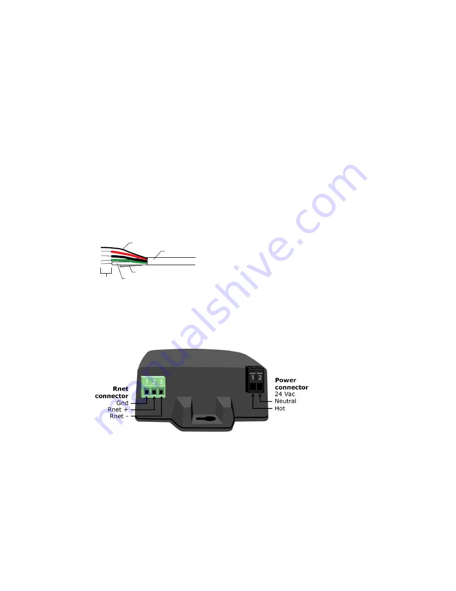
Partially cut, then bend and pull off the outer jacket of the Rnet cable(s). Do not nick the inner insulation. 


Inner insulation

Outer jacket

Foil shield

.25 in.

(.6 cm)

Shield wire


Strip about 0.25 inch (0.6 cm) of the inner insulation from each wire.  

Wire the 

Rnet +

Rnet -

, and 

Gnd 

terminals on the controller's 

Rnet

 port to the terminals of the same name on 

the Wireless Adapter's Rnet connector. 

NOTE  

If using shielded wire, connect the shield wire and the ground wire to the 

Gnd 

terminal.  


Wire the 24 Vac external power supply to the Wireless Adapter's power connector.  

Mount the Wireless Adapter by inserting 2 screws through the mounting tabs on each end of the Wireless 

Adapter. 

Apply power to the external power supply.  

Verify that the LED on top of the Wireless Adapter is blinking. See "LED" below. 

Turn on the controller's power. 


Содержание UC Open

Страница 1: ...I In ns st ta al ll la at ti io on n a an nd d S St ta ar rt t u up p G Gu ui id de e CARRIER CORPORATION 2019 A member of the United Technologies Corporation family Stock symbol UTX Catalog No 11 80...

Страница 2: ...ur local Carrier office Important changes are listed in Document revision history at the end of this document CARRIER CORPORATION 2019 All rights reserved throughout the world i Vu is a registered tra...

Страница 3: ...outputs 8 To wire inputs and outputs 9 Wiring devices to the UC Open s Rnet port 11 Rnet wiring specifications 11 To wire ZS sensors to the controller 11 To wire the Wireless Adapter for wireless sens...

Страница 4: ......

Страница 5: ...C Open controller The UC Open is a general purpose controller that provides the communications circuitry non volatile memory and removable screw terminals for I O connections Specifications Driver drv...

Страница 6: ...Local Access port For system start up and troubleshooting using Field Assistant Inputs 6 inputs configurable for thermistor or dry contact 1 and 2 are also configurable for 0 5 Vdc sensors NOTE Input...

Страница 7: ...in 13 cm Mounting dimensions C D E 5 1 4 in 13 3 cm 2 9 16 in 6 5 cm 3 16 in 5 cm Panel depth 2 in 51 mm Weight 0 6 lbs 0 27 kg BACnet support Conforms to the BACnet Advanced Application Controller B...

Страница 8: ...port page 11 Mounting the UC Open WARNING When you handle the UC Open Do not contaminate the printed circuit board with fingerprints moisture or any foreign material Do not touch components or leads H...

Страница 9: ...labeled Gnd and Hot 3 Connect the transformer wires to the screw terminal connector NOTE If using a grounded transformer connect the ungrounded lead to the Hot terminal to avoid damaging the transfor...

Страница 10: ...CAUTION The factory default setting is 00 and must be changed to successfully install your UC Open Wiring for communications The UC Open communicates using BACnet on the following types of network se...

Страница 11: ...nd 4 to MS TP BACnet MS TP The appropriate baud rate See the MS TP Baud diagram on the controller Off Off ARC156 BACnet ARC156 N A Baud rate will be 156 kbps regardless of the DIP switch settings Off...

Страница 12: ...0 33 to 2 52 Vdc All Dry contact A 3 3 Vdc wetting voltage detects contact position resulting in a 0 3 mA maximum sense current when the contacts are closed IN 1 IN 2 0 5 Vdc The input impedance of th...

Страница 13: ...hat the UC Open s power and communications connections work properly 2 Pull the screw terminal connector from the controller s power terminals labeled Gnd and Hot 3 Connect the input wiring to the scr...

Страница 14: ...IN 1 or IN 2 to the type of signal the input will receive All Thermistor Dry contact Verify the IN 5 jumper is on Rnet Port ZS sensors Wireless Adapter for wireless sensors Equipment Touch TruVu ET Di...

Страница 15: ...ions NOTE Use the specified type of wire and cable for maximum signal integrity Description 4 conductor shielded or unshielded CMP plenum rated cable Conductor 22 AWG 7x0096 bare copper if Rnet has on...

Страница 16: ...m each wire Outer Jacket Inner insulation 25 in 6 cm 3 Wire each terminal on the sensor to the same terminal on the controller See diagram below NOTE Carrier recommends that you use the following Rnet...

Страница 17: ...off the power to the controller that the Wireless Adapter will be wired to 2 Partially cut then bend and pull off the outer jacket of the Rnet cable s Do not nick the inner insulation Inner insulatio...

Страница 18: ...Rnet with ZS sensors or a Wireless Adapter use the standard 4 conductor Rnet wiring and follow the wiring instructions To wire ZS sensors to the UC Open page 11 The only device on the Rnet you can use...

Страница 19: ...erminal 5 Turn on the UC Open s power 6 Turn on the Equipment Touch To wire the TruVu ET Display WARNING Do not apply line voltage main 24 Vdc power only Wiring power Wire the TruVu ET Display 24V DC...

Страница 20: ...ll your UC Open into an i Vu Control System Use the Help in the referenced software for detailed descriptions of these procedures EquipmentBuilder or Snap 1 Use EquipmentBuilder or Snap to create cont...

Страница 21: ...gram drop down list Select the control program Not in the Control Program drop down list a Click Add New b Browse to select the control program c Click Open d Click Continue e Click Close 7 To upload...

Страница 22: ...t port Temporary or permanent user interface for start up 1 Requires a USB Link Part USB L 2 See the Equipment Touch Installation and Setup Guide for detailed instructions CAUTION If multiple controll...

Страница 23: ...ble but they will reset themselves if the condition that caused the fault returns to normal Rx Lights when the controller receives data from the network segment there is an Rx LED for Ports 1 and 2 Tx...

Страница 24: ...ry the following solutions Turn the UC Open off then on Download memory to the UC Open Replace the UC Open NOTE If you resolve the issue but the Error LED does not turn off cycle power to the controll...

Страница 25: ...ower and measure the voltage If the voltage is below 2 9 volts you need to replace the battery CAUTION Power must be ON to the UC Open when replacing the battery or your date time and trend data will...

Страница 26: ...ful interference to radio communications Operation of this equipment in a residential area is likely to cause harmful interference in which case the user will be required to correct the interference a...

Страница 27: ...erm Dry Contact Upper IN 1 IN 1 GND 0 5Vdc Lower IN 2 GND Therm Dry Contact Upper IN 2 IN 2 GND 0 5Vdc Lower IN 3 GND Therm Dry Contact N A IN 3 IN 4 GND Therm Dry Contact N A IN 4 IN 5 GND Therm Dry...

Страница 28: ...ter for wireless sensors C D To wire the controller to the network Added BACnet ARC156 connection information C D Wiring for communications Changed from Wiring the UC Open to the MS TP network C D Spe...

Страница 29: ......

Страница 30: ...CARRIER CORPORATION 2019 A member of the United Technologies Corporation family Stock symbol UTX Catalog No 11 808 464 01 1 25 2019...

Отзывы: