


53
7. Scroll through the rest of the days (press
) to to be
sure that no other days have been flagged. Suppose, for
this example, Tuesday was flagged for this period. To
change this period from YES to NO, press
,
and the display will change to TUE NO.
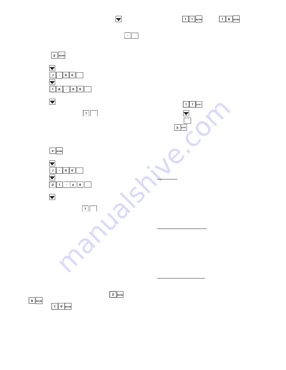
To Program Period 2:
1. Press
to enter the period 2 subfunction. The
display will read PERIOD 2.
2. Press
to scroll down to OCC.
3. Press
for 7:00 a.m.
4. Press
to scroll down to UNO.
5. Press
for 6:00 p.m.
Next are the flags for each day.
6. Press
to move to MON. Suppose that the display
reads MON NO. To change the flag so that this period
will be in effect, press
, and the display will
change to MON YES.
7. Scroll through the rest of the days to flag Tuesday for
this schedule and be sure that no other days have been
flagged.
To Program Period 3:
1. Press
to enter the period 3 subfunction. The
display will read PERIOD 3.
2. Press
to scroll down to OCC.
3. Press
for 7:00 a.m.
4. Press
to scroll down to UNO.
5. Press
for 9:30 p.m.
Next are the flags for each day.
6. Press
to move to MON. Suppose the display reads
MON YES. To change the flag so that this period will
not be in effect, press
, and the display will
change to MON NO. Do the same for Tuesday. Scroll
through the rest of the days to flag Wednesday for this
schedule and be sure that no other days have been
flagged.
To Program Periods 4 and 5: These can be programmed in the
same manner as above, flagging Thursday and Friday yes for
period 4 and Saturday yes for period 5.
To Program Periods 6, 7, and 8: Since these schedules are not
used in this example, they should be programmed for OCC
00.00 and UNO 00.00.
NOTE: When a day is flagged yes for 2 overlapping periods,
occupied time will take precedence over the unoccupied
time. Occupied times can overlap in the schedule with no
consequence.
The same scheduling procedures can be used to set optional
discrete output schedule II. Subfunctions
through
define the schedule of the rooftop unit (schedule I).
Subfunction
provides the override for schedule II.
Subfunctions
through
define schedule
of optional discrete output (schedule II).
NOTE: If the unit is connected to a DAV system, the unit time
schedule is ignored. The time schedule should still be entered
into the unit in case communications are lost with the network.
Start Unit
1. Put the ON/OFF switch in the ON position. Close the
control circuit breaker (CCB), which will energize the
control circuit and the crankcase heaters.
2. Using the HSIO keypad or CCN ComfortWORKS®
software, verify that no alarms have been detected.
3. Ensure that quick test has been performed to make sure
controls are operating properly. Refer to Quick Test
section on page 86 for instructions on quick test.
4. Using the HSIO keypad, put unit into the run mode:
a. Press
.
b. Press
.
c. Press
. This will put unit in "RUN" mode.
Press
and the unit changes status from mode 25
(standby) to mode 32 (occupied) or mode 27 (unoccupied), de-
pending on the programmed time schedule. When the unit re-
ceives a call for cooling or heating (either from the internal
control or the CCN Network command), the unit will initiate
activity to meet the respective set point value.
Operating Sequences
SUPPLY FAN
VAV Units — During Occupied periods, the control will ener-
gize the supply fan contactor. The contactor will close, energiz-
ing supply fan motor. Fan wheel will turn. Airflow Switch (dif-
ferential pressure switch) contacts close, providing discrete in-
put (DI) to Channel 12 (Closed = Fan ON). Fan operation will
continue through the Occupied period.
During Unoccupied period with demand, the control will
energize fan contactor when demand is sensed. After fan status
is confirmed, operating routines will start. When demand is re-
moved, routines will end and fan will shut off.
CV Units, Continuous Fan — During Occupied periods, the
control will energize the supply fan contactor. The contactor
will close, energizing supply fan motor. Fan wheel will turn.
Airflow Switch (differential pressure switch) contacts close,
providing discrete input (DI) to Channel 12 (Closed = Fan
ON). Fan operation will continue through the Occupied period.
During Unoccupied period with demand, the control will
energize fan contactor when demand is sensed. After fan status
is confirmed, operating routines will start. When demand is re-
moved, routines will end and fan will shut off.
CV Units, Automatic Fan — Fan will be turned OFF during
Occupied period when there is no demand for heating or cool-
ing operation. When demand is sensed, control will energize
fan contactor and initiate cooling cycle. Fan status will be con-
firmed. When demand is removed, routines will terminate and
fan will be shut off.
ENTER
ENTER
ENTER
ENTER
ENTER
ENTER
ENTER
CLEAR


