KGAET0201ETK: Installation Instructions
Manufacturer reserves the right to change, at any time, specifications and designs without notice and without obligations.
11
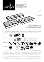
L13F008A
Fig. 7 – Vent Located Below Floor with Downflow Furnace and Side Venting
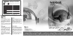
L13F008B
Fig. 8 – Vent Located Below Floor with Downflow Furnace and Side Venting
Representative drawing only, some models may vary in appearance
APPROVED
SUB--BASE OR
COIL CABINET
TO CODE--APPROVED DRAIN
OR CONDENSATE PUMP
F
D & E
FLOOR
JOISTS
G
B
A
AIR FLOW
H
SLOPE UP TO
TERMINATION
1/4-
IN. PER FOOT
Two inch pipe shown.
When another size pipe is
used, discard the 2-in. tee
in the kit and use a field
supplied tee that is the
same diameter as the pipe
being used.
Representative drawing only, some models may vary in appearance
CONFIGURATION FOR VENT AND
/
OR COMBUSTION AIR PIPIING
(See NOTES in Figure 1)
APPROVED
SUB--BASE OR
COIL CABINET
TO CODE--APPROVED DRAIN
OR CONDENSATE PUMP
F
D & E
FLOOR
JOISTS
G
B
A
H
AIR FLOW
SLOPE UP TO
TERMINATION
1/4-
IN. PER FOOT
Two inch pipe shown.
When another size pipe is
used, discard the 2-in. tee
in the kit and use a field
supplied tee that is the
same diameter as the pipe
being used.