


18
Enable-Off-Remote Switch (SW1)
The position of the Enable-Off-Remote switch is ignored except
when the Remote control type is selected. Refer to the Machine
Control Methods section on page 25 for more details. A selection
for Machine Control Method must also be made along with the
correct position of the Enable-Off-Remote Switch. This switch is
installed in all units. It is a 3-position switch used to control the
chiller. When switched to the Enable position, the chiller will ig-
nore the field-supplied Remote Contacts, enabling the unit all of
the time. When switched to the Off position, the chiller will shut
down if running. This allows for local (at the unit) override of the
Remote Contact input. When switched to the Remote position, a
field-installed dry contact can be used to start and stop the chiller.
The contacts must be capable of handling a 24 VAC, 50 mA load.
In the Enable and Remote Contact (dry contacts closed) positions,
the chiller is allowed to operate and respond to the scheduling con-
figuration and set point data.
Emergency On/Off Switch (SW2)
This switch is installed in all units. The Emergency On/Off switch
should only be used when it is required to shut the chiller off im-
mediately. Power to all modules is interrupted when this switch is
off and all outputs from these modules will be turned off.
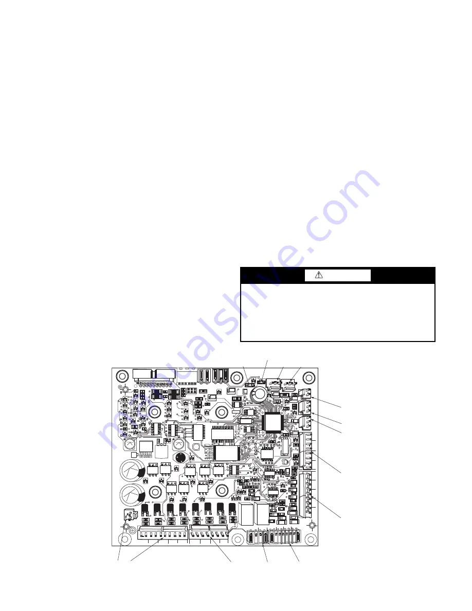
Energy Management Module (EMM)
The EMM is available as a factory-installed option or as a
field-installed accessory. See Fig. 21. When the EMM module
is field-installed, the Carrier Controller must be set up to com-
municate with the EMM module (
Main Menu
Configura-
tion Menu
Factory Parameters
Energy Management
Module
Yes
). The Energy Management Module allows the
following functions:
• Chilled Water Temperature Reset — Resets the chilled wa-
ter set point by the following methods:
a. 4 to 20 mA Input: A field-supplied signal generator
and
1
/
2
-watt, 250-ohm resistor are required.
b. Space Temperature: A field-supplied space tempera-
ture sensor is required.
• Demand Limit — Limits the capacity of the machine from
unit capacity by the following methods:
a. 4 to 20 mA Input: A field-supplied signal generator
and
1
/
2
-watt, 250-ohm resistor are required.
b. 2 or 3-Step Switch Control: A field-supplied dry con-
tact switch is required. (One-Step Demand Limit does
not require the EMM.)
• Occupancy Override — Extends the occupied period for
machine operation. A field-supplied dry contact switch is
required.
• Remote Chiller Lockout — Disables the chiller when
closed. A field-supplied dry contact switch is required.
• Ice Done Control Switch — Signals the machine to exit
the Ice Build mode and enter an unoccupied time period. A
field-supplied dry contact switch is required.
The following status functions are available with the EMM board:
• Capacity Output Signal — A 0 to10 vdc analog output sig-
nal indicating chiller capacity is available.
• Shutdown Status Relay — A 24 vac output signal indicat-
ing that the machine is shutting down.
• Alert Relay — A 24 vac output signal indicating the unit
has an active alert.
• Compressor Run Status — A 24 vac output signal (one for
compressor A, one for compressor B), indicating the com-
pressor is on.
The EMM communicates the status of all inputs with the Carri-
er Controller module, and the controls adjusts the control point,
capacity limit, and other functions according to the inputs re-
ceived. See Table 12 for EMM board inputs and outputs.
Fig. 21 — Energy Management Module
CAUTION
Care should be taken when interfacing with other manufactur-
er’s control systems due to possible power supply differences,
full wave bridge versus half wave rectification, which could
lead to equipment damage. The two different power supplies
cannot be mixed. Carrier Controller controls use half wave
rectification. A signal isolation device should be utilized if a
full wave bridge rectifier signal generating device is used.
221
221
221
221
100K
100K
100K
100K
100K
CH
17
CH
17
CH
16
CH
CH
1
8
CH
19
CH
20
CH
22
CH
21
CH
2
3
24 V
A
C
12 11
CH 11
b
CH 12
CH 1
3
CH 14
CH 15
CH
1
CH
2
CH
3
CH
4
CH 5
CH 6
CH 7
S
IO LEN
+ G -
+ G -
S
IO LEN
J
8
J7B
J7A
J6
J5
J4
J
3
J2B
J2A
J1
CH
24
CH
25
CH
8
CH
9
CH
10
CH
11
a
J9A
J9B
RED LED -
S
TATU
S
GREEN LED - LEN
(Loc
a
l E
qu
ipment Network)
Содержание AquaForce 30XV140
Страница 79: ...79 Fig 76 VFD Communication Wiring Compressor A B Fan VFD A1 A2 B1 B2...
Страница 82: ...82 Fig 81 VFD Compressor Locations 30XV225 325 30XV350 500 30XV140 325 COMPRESSOR A VFD COMPRESSOR B VFD...
Страница 228: ...228 Fig 90 30XV Typical Field Wiring Schematic cont...
Страница 229: ...229 Fig 91 30XV Standard Tier 140 275 All Voltages Power Schematic NOTE See Legend on page 226...
Страница 230: ...230 Fig 92 30XV Standard Tier 300 325 All Voltages Power Schematic NOTE See Legend on page 226...
Страница 231: ...231 Fig 92 30XV Standard Tier 300 325 All Voltages Power Schematic cont NOTE See Legend on page 226...
Страница 232: ...232 Fig 93 30XV Standard Tier 350 500 380 400 415 440 460 575v Power Schematic NOTE See Legend on page 226...
Страница 233: ...233 Fig 93 30XV Standard Tier 350 500 380 400 415 440 460 575v Power Schematic cont NOTE See Legend on page 226...
Страница 234: ...234 Fig 94 30XV High Tier 350 450 All Voltages Mid Tier 350 500 All Voltages Power Schematic NOTE See Legend on page 226...
Страница 235: ...235 Fig 95 30XV Mid Tier 140 All Voltages 160 275 380 400 415 440 460 575v Power Schematic NOTE See Legend on page 226...
Страница 236: ...236 Fig 96 30XV High Tier 140 200 380 400 415 440 460 575v Power Schematic NOTE See Legend on page 226...
Страница 237: ...237 Fig 97 30XV High Tier 140 200 208 230v Mid Tier 160 200 208 230v Power Schematic NOTE See Legend on page 226...
Страница 238: ...238 Fig 98 30XV High Tier 225 325 All Voltages Mid Tier 300 325 All Voltages Power Schematic NOTE See Legend on page 226...
Страница 240: ...240 Fig 99 30XV Communication Wiring...
Страница 241: ...241 Fig 100 30XV 115V Control Wiring All Tonnages All Voltages...
Страница 242: ...242 Fig 101 30XV 24V Control Wiring 30XV140 325 All Voltages...
Страница 243: ...243 Fig 101 30XV 24V Control Wiring 30XV140 325 All Voltages cont...
Страница 244: ...244 Fig 102 30XV 24V Control Wiring 30XV350 500 All Voltages...
Страница 245: ...245 Fig 102 30XV 24V Control Wiring 30XV350 500 All Voltages cont...
Страница 246: ...246 Fig 103 Component Arrangement Diagram for 30XV140 325...
Страница 247: ...247 Fig 103 Component Arrangement Diagram for 30XV140 325 cont...
Страница 248: ...248 Fig 104 Component Arrangement Diagram for 30XV350 500...
Страница 337: ...337 APPENDIX J FACTORY SUPPLIED PUMPS cont Fig L System Information...
Страница 338: ...338 APPENDIX J FACTORY SUPPLIED PUMPS cont Fig M Unit and Language Settings...
Страница 339: ...339 APPENDIX J FACTORY SUPPLIED PUMPS cont Fig N Hand Off Auto This is set in Auto mode for sensorless operation...
Страница 341: ...341 APPENDIX J FACTORY SUPPLIED PUMPS cont Fig P Data Input 2...
Страница 342: ...342 APPENDIX J FACTORY SUPPLIED PUMPS cont Fig Q Data Input 3...
Страница 347: ...347 APPENDIX J FACTORY SUPPLIED PUMPS cont Fig U Pump Wiring Diagram...


