34
11 - STANDARD MAINTENANCE
Air conditioning equipment must be maintained by profes-sional
technicians, whilst routine checks can be carried out locally by
specialised technicians. See the standard EN 378-4.
Simple preventive maintenance will allow you to get the best
performance from your HVAC unit:
-
improved cooling performance
-
reduced power consumption
-
prevention of accidental component failure
-
prevention of major time-consuming and costly inter-
ventions
-
protection of the environment
There are five maintenance levels for HVAC units, as defined by
the AFNOR X60-010 standard.
11.1 - Level 1 maintenance (see note)
Simple procedure can be carried out by the user:
-
Visual inspection for oil traces (sign of a refrigerant leak)
-
Air heat exchanger (condenser) cleaning - see chapter
“Condenser coil - level 1”
-
Check for removed protection devices, and badly closed
doors/covers
-
Check the unit alarm report when the unit does not work (see
report in the 30XA/30XAS/30XW Touch Pilot control manual).
General visual inspection for any signs of deterioration.
11.2 - Level 2 maintenance (see note)
This level requires specific know-how in the electrical, hydraulic
and mechanical fields. It is possible that these skills are available
locally: existence of a maintenance service, industrial site,
specialised subcontractor.
In these cases, the following maintenance operations are
recommended.
Carry out all level 1 operations, then:
-
At least once a year tighten the power circuit electrical
connections (see tightening torques table).
-
Check and re-tighten all control/command connections, if
required (see tightening torques table).
-
Remove the dust and clean the interior of the control boxes,
if required.
-
Check the presence and the condition of the electrical
protection devices.
-
Check the correct operation of all heaters.
-
Replace the fuses every 3 years or every 15000 hours (age-
hardening).
-
Replace the control box cooling fans used with option 22
(with designation EF22_) every five years.
-
Check the height of the anti-vibration mountings (located
between the compressor rails and the unit chassis) after 5
years of operation, and then each year. When the total
minimum height of the mountings is less than 25 mm replace
the mountings.
-
Check the water connections.
-
Purge the water circuit (see chapter “Water flow control
procedure”).
-
Clean the water filter (see chapter “Water flow control
procedure”).
-
Fully clean the condensers with a low-pressure jet and a
bio-degradable cleaner (counter-current cleaning - see
chapter “Condenser coil - level 2).
-
Replace the stuffing box packing of the pump after 10000
hours of operation.
-
Check the unit operating parameters and compare them with
previous values.
-
Keep and maintain a maintenance sheet, attached to each
HVAC unit.
-
Check correct operation of the capacitor (power factor
correction option 231).
All these operations require strict observation of adequate safety
measures: individual protection garments, compliance with all
industry regulations, compliance with applicable local regulations
and using common sense.
11.3 - Level 3 (or higher) maintenance (see
note)
The maintenance at this level requires specific skills/approval/
tools and know-how and only the manufacturer, his representative
or authorised agent are permitted to carry out these operations.
These maintenance operations concern for example:
-
A major component replacement (compressor, evaporator)
-
Any intervention on the refrigerant circuit (handling refrigerant)
-
Changing of parameters set at the factory (application
change)
-
Removal or dismantling of the HVAC unit
-
Any intervention due to a missed established maintenance
operation
-
Any intervention covered by the warranty
NOTE: Any deviation or non-observation of these maintenance
criteria will render the guarantee conditions for the HVAC unit
nul and void, and the manufacturer, Carrier France, will no
longer be held responsible.
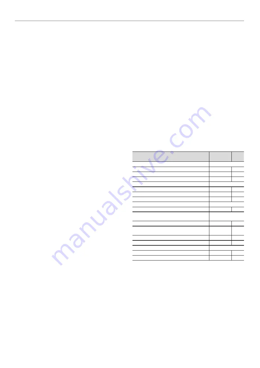
11.4 -
Tightening torques for the main electrical
connections
Component
Designation
in the unit
Value
(N·m)
Screw on bus bar, customer connection
M8
-
18
M10
L1 /L2 /L3
30
Soldered screw PE, customer connection (M12)
PE
70
Tunnel terminal screw, compressor contactor
Contactor 3RT104_
-
5
Contactor 3RT105_
-
11
Contactor 3RT106_
KM_
21
Tunnel terminal screw, current transformer
Size 2 (3RB2956_)
-
11
Compressor earth terminal in the power wiring
control box
Terminal M8
Gnd
30
Compressor phase connection terminals M12
1 /2 /3 /4 /5
/6 sur EC_
25
Compressor earth connection
Gnd sur EC_
25
Tunnel terminal screw, disconnects 3RV1011_
QF_ /QM_
1
Tunnel terminal screw, hydraulic pump contactor
Contactor 3RT101_
KM90_
1
Contactor 3RT102_
-
2.2
Содержание Aquaforce 30XAS Series
Страница 2: ...2...


