


Reviews:
No comments
Related manuals for 1C3472

SERHQ020BAW1
Brand: Daikin Pages: 60
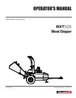
BXT52S
Brand: Wallenstein Pages: 76

ECOWISE RTAF HE
Brand: Trane Pages: 124

A240 ZKX
Brand: Jensen Pages: 54

Angeln
Brand: Jensen Pages: 39

YST
Brand: York Pages: 90

1888
Brand: Moser Pages: 116

HC6000
Brand: Remington Pages: 164

TKG HC 18
Brand: Team Kalorik Pages: 44

SP-1810P
Brand: Sapir Pages: 15

HC1000
Brand: Zelmer Pages: 96

MILLENNIUM YS
Brand: York Pages: 48

ACFR MICRO E 100H
Brand: Accorroni Pages: 36

EWAA011-016DAV3P
Brand: Daikin Pages: 20

247.776360
Brand: Craftsman Pages: 40

OALC 010
Brand: omran tahvieh Pages: 38

NRA
Brand: AERMEC Pages: 4

BC-10
Brand: Randell Pages: 1


