


6
−
7
T
−
318
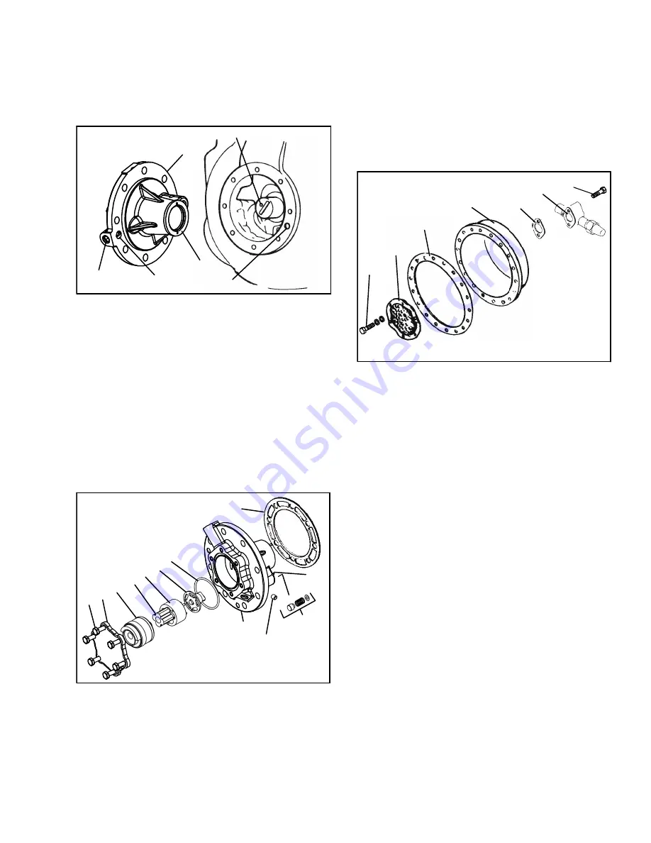
f. If necessary, remove the oil return check valve (see
Figure 6-7). Inspect it for proper operation (flow in
one direction only). Replace the assembly with a new
unit if check valve operation is impaired.
g. To remove the oil pump (see Figure 6-8) remove eight
cap screws, oil pump bearing head assembly, gasket,
and thrust washer.
2
1
3
4
5
Set screw must be removed.
1. Oil Pump & Bearing
Head
2. Thrust Washer
3. Oil Pickup Tube
4. Oil Inlet Port
5. Oil Pump Inlet
Figure 6-8 Oil Pump and Bearing Head
NOTE
If the oil pump was not operating properly, the
entire oil pump & bearing head assembly must
be replaced. Individual parts are not available. If
the pump requires inspection or cleaning, dis-
assemble and reassemble by referring to
Figure 6-9. Clean all parts and coat all moving
parts with compressor oil before proceeding
with reassembly.
12
1
2 3
4
5
6
7
8
9
10
11
1. Cap screws
2. Cover
3. Reversing Assembly
4. Pinion
5. Gear
6. Drive
7. O-Ring
8. Oil Pump & Bearing
9. Set Screw
10. Relief Valve
11. Pin
12. Gasket
Figure 6-9 Low Profile Oil Pump
h. Be very careful not to damage the motor windings
when removing the motor end cover (see
Figure 6-10), as the cover fits over the winding coils.
Loosen the cap screws, break the seal, and then re-
move all cap screws except one in the top of the
cover. While holding the cover in place, remove the
remaining cap screw. Do not allow the cover to drop
from its own weight. To prevent striking the winding,
remove the cover horizontally and in line with the
motor axis.
1. Strainer Screws and
Washers
2. Suction Strainer
3. Motor End Cover
Gasket
4. Motor End Cover
5. Valve Gasket
6. Suction Service Valve
7. Valve Cap screw
Figure 6-10 Motor End Cover
i. Remove the refrigerant suction strainer. If it is
removed with ease, it may be cleaned with solvent
and replaced. If the strainer is broken, corroded or
clogged with dirt that is not easily removed, replace
the strainer. Install new gaskets upon reassembly.
j. Block the compressor crankshaft so that it cannot
turn. Use a screwdriver to bend back the tabs on the
lockwasher, and remove the equalizer tube and lock
screw assembly (see Figure 6-11). The slingers at
the end of the tube draw vapor from the crankcase.
Remove the rotor using a jack bolt. Insert a brass plug
into the rotor hole to prevent damage to the end of the
crankshaft.
k. If the piston rings extend beyond the cylinder tops, the
pistons can be pulled through the bottom plate open-
ing after the piston rings are compressed. A piston
ring compressor will facilitate removal. Each piston
pin is locked in place by lock rings, which are snapped
into grooves in the piston wall (see Figure 6-12).
l. Since the stator cannot be replaced in the field, the
terminal plate assembly need not be disturbed unless
a leak exists and the plate assembly needs to be re-
placed. If no terminal plate repair is required, proceed
with reassembly.
Содержание 69NT40-541-300
Страница 2: ......
Страница 4: ......
Страница 20: ......
Страница 32: ......
Страница 128: ......
Страница 131: ...7 3 T 318 Based on Drawing 62 66058 Figure 7 2 SCHEMATIC DIAGRAM Units with 3 Phase Evaporator Motors...
Страница 133: ...7 5 T 318 6 Heater FCCH FCCH Figure 7 4 SCHEMATIC DIAGRAM Units with Normal Evaporator Fan Capability...
Страница 134: ...7 6 T 318 FCCH FCCH Figure 7 5 SCHEMATIC DIAGRAM Units with Single Evaporator Fan Capability...
Страница 136: ...7 8 T 318 To ST10 To TRX2 To QC1 To QC1 To QC1 To MC6 CONTROLLER Figure 7 7 SCHEMATIC DIAGRAM Emergency Bypass...
Страница 138: ...7 10 T 318 Based on Drawing 62 66058 Figure 7 9 UNIT WIRING DIAGRAM Units with 3 Phase Evaporator Motors Sheet 1 of 2...
Страница 139: ...7 11 T 318 Based on Drawing 62 66058 Figure 7 10 UNIT WIRING DIAGRAM Units with 3 Phase Evaporator Motors Sheet 2 of 2...
Страница 144: ......
Страница 150: ......
Страница 151: ......