


T-318
3
−
3
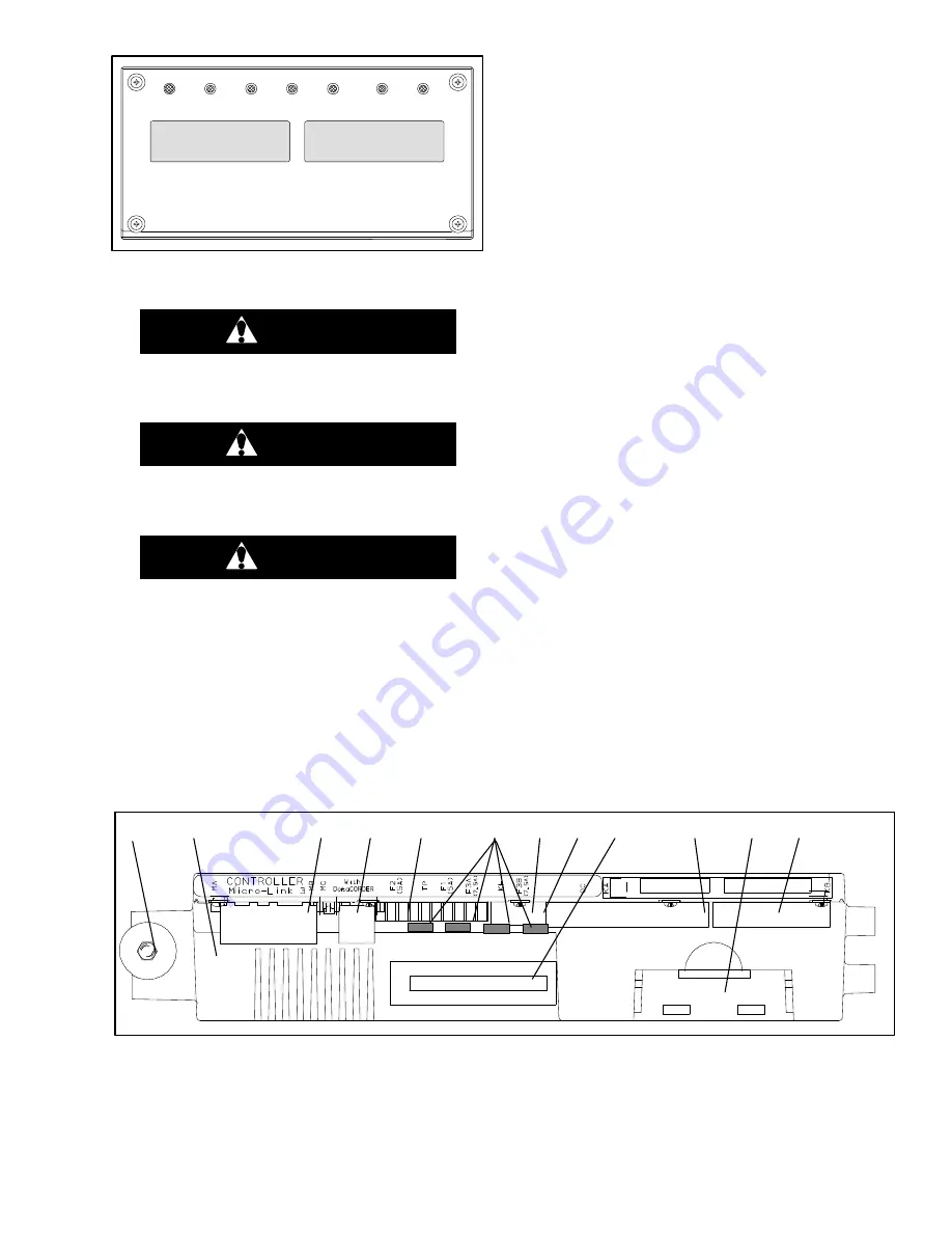
COOL
HEAT DEFROST IN RANGE ALARM
SUPPLY RETURN
SETPOINT/Code
AIR TEMPERATURE/Data
Figure 3-3 Display Module
3.1.3 Controller
CAUTION
Do not remove wire harnesses from con-
troller unless you are grounded to the unit
frame with a static safe wrist strap.
CAUTION
Unplug all controller wire harness connec-
tors before performing arc welding on any
part of the container.
CAUTION
Do not attempt to use an ML2i PC card in an
ML3 equipped unit. The PC cards are physi-
cally different and will result in damage to
the controller.
NOTE
Do not attempt to service the controller. Break-
ing the seal will void the warranty.
The Micro-Link 3 controller is a single module
microprocessor as shown in Figure 3-4. It is fitted with
test points, harness connectors and a software card
programming port.
3.2 CONTROLLER SOFTWARE
The controller software is a custom designed program
that is subdivided into the configuration software and the
operational software. The controller software performs
the following functions:
a. Control supply or return air temperature to required
limits, provide modulated refrigeration control, elec-
tric heat control, and defrost. Defrost is performed to
clear buildup of frost and ice from the coil to ensure
continuous conditioned air delivery to the load.
b. Provide default independent readouts of set point and
supply or return air temperatures.
c. Provide ability to read, and if applicable, modify the
configuration software variables, operating software
function codes, and alarm code indications.
d. Provide a Pre-trip step-by-step checkout of
refrigeration unit performance, including proper
component operation, electronic and refrigeration
control operation, heater operation, probe calibration,
pressure limiting, and current limiting settings.
e. Provide battery-powered ability to access or change
selected codes and set points without AC power
connected.
f. Provide the ability to reprogram the software through
the use of a memory card.
3.2.1 Configuration Software (CnF Variables)
The configuration software is a variable listing of the
components available for use by the operational
software. This software is factory-installed in
accordance with the equipment fitted and options listed
on the original purchase order. Changes to the
configuration software are required only when a new
controller has been installed or a physical change has
been made to the unit such as the addition or removal of
an option. A configuration variable list is provided in
Table 3-4. Change to the factory
−
installed configuration
software is achieved via a configuration card or by
communications.
1. Mounting Screw
2. Micro-Link 3 Controller
3. Connectors
4. Test Points
5. Fuses
6. Control Circuit Power Connection
located on back of controller)
7. Software Programming Port
8. Battery Pack
Figure 3-4 Control Module
Содержание 69NT40-541-300
Страница 2: ......
Страница 4: ......
Страница 20: ......
Страница 32: ......
Страница 128: ......
Страница 131: ...7 3 T 318 Based on Drawing 62 66058 Figure 7 2 SCHEMATIC DIAGRAM Units with 3 Phase Evaporator Motors...
Страница 133: ...7 5 T 318 6 Heater FCCH FCCH Figure 7 4 SCHEMATIC DIAGRAM Units with Normal Evaporator Fan Capability...
Страница 134: ...7 6 T 318 FCCH FCCH Figure 7 5 SCHEMATIC DIAGRAM Units with Single Evaporator Fan Capability...
Страница 136: ...7 8 T 318 To ST10 To TRX2 To QC1 To QC1 To QC1 To MC6 CONTROLLER Figure 7 7 SCHEMATIC DIAGRAM Emergency Bypass...
Страница 138: ...7 10 T 318 Based on Drawing 62 66058 Figure 7 9 UNIT WIRING DIAGRAM Units with 3 Phase Evaporator Motors Sheet 1 of 2...
Страница 139: ...7 11 T 318 Based on Drawing 62 66058 Figure 7 10 UNIT WIRING DIAGRAM Units with 3 Phase Evaporator Motors Sheet 2 of 2...
Страница 144: ......
Страница 150: ......
Страница 151: ......