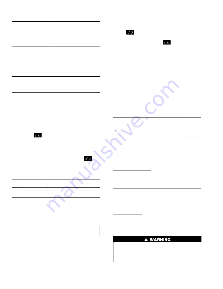
Table 9 — DIP Switch Functions
DIP SWITCH
NO.
SELECTED FUNCTION*
1
Type of Reset
2
Reset
3
Pull Down Limit
4
Not Used
5
Demand Limit
6
1 Unloader
7
2 Unloaders
8
Brine
LEGEND
DIP — Dual In-Line Package
*Refer to Table 8, Quick Test steps 3. through 1.0.
Table 10 — Potentiometer Locations
POTENTIOMETER
LOCATION
P1 — Leaving Fluid Set Point
Set Point Board (Standard)
P3 — Reset Limit Set Point
Accessory Board (Option)
P4 — Demand Limit Set Point
Accessory Board (Option)
P5 — Reset Ratio Set Point
Accessory Board (Option)
P6 — Reset Temp Set Point
Accessory Board (Option)
START-UP AND OPERATION
NOTE: Complete Start-Up Checklist at center of publica-
tion (page CL-1) prior to starting unit.
Digital Display Action —
The electronic control sys-
tem uses a 2-digit LED display located on display set point
board (see Fig. 19) to show operational information and di-
agnostic codes.
When control ON-OFF switch is turned to ON position,
display shows
for 2 minutes to indicate control is in
initialization mode. The EXV will be closed as part of ini-
tialization sequence. This does not occur on FIOP units, where
a conventional TXV is used.
After a 2-minute period, display turns off and unit is
allowed to start. If button is pressed after the
has
been removed from display, operational status codes or
diagnostic information will be shown as long as button is
held in. Code numbers on display have following
significance:
CODE
NUMBER
OPERATIONAL
STATUS
0-12
Capacity stage
20-26
Operational information
51-87
Overload information
Under normal operation, only stage number is displayed.
If an operational status code or an overload code is dis-
played, the display rotates every 2 seconds and displays up
to 3 numbers. Overload information will take priority over
all other codes. The codes are stored by the microprocessor
as long as board is energized.
IMPORTANT: The alarm memory is cleared when con-
trol power is removed.
Actual Start-Up —
Actual start-up should be done only
under supervision of a qualified refrigeration mechanic.
1. Be sure all service valves are open. The unit is shipped
from the factory with the suction, discharge, and liquid
line service valves closed.
2. Set leaving fluid temperature. No cooling range adjust-
ment is necessary.
3. If accessory reset boards are used, set potentiometers prop-
erly. Refer to Controls and Troubleshooting literature for
details.
4. Start chilled fluid pump.
5. Turn ON-OFF switch to ON position. The display will
read
. During this time the machine checks all po-
tentiometers and thermistors for valid readings. In
approximately 2 minutes, the
reading is no longer
displayed, and the machine is operational.
Allow the unit to operate and confirm that everything is
functioning properly. Check the leaving fluid temperature and
be sure that it agrees with the set point potentiometer P1. If
the temperature setting does not agree, the set point can be
compensated by shifting the control point slightly. If tem-
perature reset is in effect, the leaving fluid temperature may
not agree with the set point.
Operating Limitations
TEMPERATURES (See Table 11) — If unit is to be used in
an area with high solar radiation, mounted position should
be such that control box is not exposed to direct solar
radiation. Exposure to direct solar radiation could affect the
temperature switch controlling cooler heaters.
Table 11 — Temperature Limits
TEMPERATURES
F
C
Maximum Ambient Temp
125
52
Minimum Ambient Temp
0
−18
Maximum Cooler EWT*
95
35
Maximum Cooler LWT
70
21
Minimum Cooler LWT†
40
4.5
LEGEND
EWT — Entering Fluid (Water) Temperature
LWT — Leaving Fluid (Water) Temperature
*For sustained operation, it is recommended that EWT
NOT exceed
85 F (29.4 C).
†Unit and/or DIP (dual-in-line package) switch requires modification
below this temperature.
Low-Ambient Operation — If operating temperatures be-
low 0° F (−18 C) are expected, refer to separate installa-
tion instructions for low-ambient operation/Motormaster
t
III
control. Contact your Carrier representative for details.
High Cooler LCWT (Leaving Chilled Water [Fluid] Tem-
perature) — During start-up with leaving fluid temperatures
above approximately 60 F (16 C), expansion valves (EXV
and FIOP TXV for 080-110 sizes) limit suction pressure
to approximately 90 psig (620 kPa) to avoid overloading
compressor.
Low Cooler LCWT — Application of chillers within 39.9 F
to 34 F (4.4 C to 1.1 C) temperature range is possible in
some situations with proper field change of control config-
uration. This requires that DIP switch no. 8 (brine switch) of
J11 on the processor board be set to ON position. See
Tables 8 and 9.
Do not operate with leaving water temperature below
34 F (1.1 C). Application in the range 34 F to 15 F
(1° C to −9.4 C) requires chiller with factory modifi-
cation for brine duty (only applicable to certain units).
Contact your Carrier representative for details.
50


