CARLO GAVAZZI SM2H21 Скачать руководство пользователя страница 3

Technical data

Power supply

24 Vdc ±10%, 2 W, Class 2

24 Vac -15/+10% 50-60 Hz, 4.5 VA, Class 2

Overvoltage category III

Short circuit protection internal PTC

Rated insulation voltage 4 kV

Input current

Typical 5mA

Output type

Voltage free contact output, relays with forcibly 

guided contacts

Max current rating - 

single output

@ 60°C (140°F) operating temperature:

AC 1: 250V / 6A / 2000 VA - AC 15: 230V / 3A

DC 1: 24V / 6A - DC 13: 24V / 2.5A / 0.1 Hz

Pilot duty: B300 / R300

Max. total current 

Σ

 Ith²

Spacing between modules ≥100mm: 72A² @40°C 

(104°F) ambient temperature

Modules mounted stacked: 26A² @25°C (77°F) 

ambient temperature

Please refer to the derating curves in chapter 12**

Protection grade

IP40 on frontal part of the housing, IP20 on the 

terminals. The device has to been installed in a 

cabinet with protection degree of IP54.

Operating temperature

-25 ÷ +60°C (-13 ÷ 140°F), UL: +40°C (104°F)

Storage temperature

-30 ÷ +70°C (-22 ÷ 158°F)
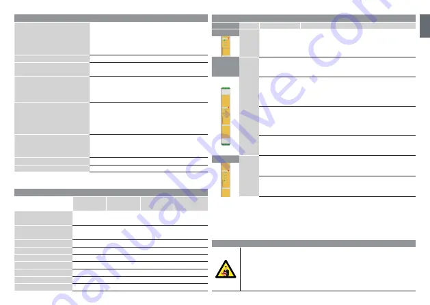
LED information

LED

Color

Status

Meaning

Power

Green

ON

SM is powered

Input 1 

Input 2

Yellow

Input 1 OFF

Input 2 OFF

The safety devices connected to the inputs 1 and 

2 are not active (e.g. contacts open); the safety 

module cannot enable the safety outputs

Input 1 ON

Input 2 OFF

The safety device connected to the input 1 is 

active (e.g. contact closed), while the input 2 is 

not active (e.g. contact open); the safety module 

cannot enable the safety outputs

Input 1 OFF

Input 2 ON

The safety device connected to the input 2 is 

active (e.g. contact closed), while the input 1 is 

not active (e.g. contact open); the safety module 

cannot enable the safety outputs

Input 1 ON

Input 2 ON

The safety devices connected to the inputs 1 and 

2 are active (e.g. contacts closed); the safety 

module can enable the safety outputs

Channels

Green

OFF

The NO safety outputs are open and the NC auxi-

liary output is closed

ON

The NO safety outputs are closed and the NC 

auxiliary output is open

Wiring information

Max. terminal tightening torque: 0.5Nm (for all connections)
To prevent contact welding, a fuse should be connected on the output contacts.

Sufficient fuse protection must be provided on all output contacts with capacitive and inductive 

loads. Ensure the wiring and EMC requirements of IEC 60204-1 are met.
It is good practice to separate the power supply of the control unit from that of other electrical 

devices (e.g. frequency drives, electric motors, inverters) or other sources of disturbance.
Use conductors with section: 0,2 - 2,5 mm² (24 - 14 AWG)

EN

Safety parameters

SMS20

SMS31

SMSA31

SM2H21

SME41

ISO 13849-1

Safety Category

Cat. 4

Cat. 4

Cat. 4

Cat. 4***

ISO 13849-1

Performance Level

PL e

PL e

PL e

PL e***

DIN EN 81-20

Certified

DIN EN 81-50

Certified

MTTF

D

 [a]

420,8

420,8

422,1

363,4

PFH

D

 [1/h]

1,85 E-10

1,85 E-10

1,35 E-10

1,59 E-10

DCavg

99%

99%

99%

99%***

ß

5,00 E-02

5,00 E-02

5,00 E-02

5,00 E-02

ß

D

2,00 E-02

2,00 E-02

2,00 E-02

2,00 E-02

***The SME41 is an expansion module with no internal diagnostics. To attain Cat 4, PL e 

according to EN ISO 13849-1, the SME41 must be used with a Cat 4, PL e master module 

and the NC feedback output of SME41 (contacts 51-52) must be connected in series with 

the start signal of the master module (as shown in sections 10.2.2 and 10.2.3)**. This 

must be done to prevent any start/restart of the system if an internal failure in the SME41 

has occurred.

Содержание SM2H21

Страница 1: ...tartanleitung Gu a de inicio r pido Guida rapida Guide de d marrage rapide Hurtig start guide EN IT DE FR ES DA ZH 15029964 Rev 0 Safety modules 2020 CARLO GAVAZZI Industri A S Carlo Gavazzi Industri...

Страница 2: ...tart S11 S12 input channel 1 S21 S22 input channel 2 Y1 Y2 NC feedback input A1 power supply 24 Vdc Vac A2 power supply 24 Vdc Vac 13 14 NO safety output 23 24 NO safety output 33 34 NO safety output...

Страница 3: ...e safety outputs Input 1 ON Input 2 ON The safety devices connected to the inputs 1 and 2 are active e g contacts closed the safety module can enable the safety outputs Channels Green OFF The NO safet...

Страница 4: ...anuale automatico X1 X3 start manuale monitorato S11 S12 ingresso canale 1 S21 S22 ingresso canale 2 Y1 Y2 ingresso di retroazione NC A1 alimentazione 24 Vcc Vca A2 alimentazione 24 Vcc Vca 13 14 usci...

Страница 5: ...pu abilitare le uscite di sicurezza Ingresso 1 ON Ingresso 2 ON I dispositivi di sicurezza collegati agli ingressi 1 e 2 sono attivi ad es Contatti chiusi il modulo di sicurezza pu abilitare le uscit...

Страница 6: ...ter manueller Start S11 S12 Kanal 1 Eingang S21 S22 Kanal 2 Eingang Y1 Y2 NC R ckf hr Eingang A1 Stromversorgung 24 Vdc Vac A2 Stromversorgung 24 Vdc Vac 13 14 NO Sicherheitsausgang 23 24 NO Sicherhei...

Страница 7: ...ht freigeben Eingang 1 EIN Eingang 2 EIN Die an Eing ngen 1 und 2 angeschlossenen Sicherheitsger te sind aktiv d h Kontakte sind geschlossen das Sicherheitsmodul kann die Sicherheitsausg nge freigeben...

Страница 8: ...nuel automatique X1 X3 d marrage manuel surveill S11 S12 entr e voie 1 S21 S22 entr e voie 2 Y1 Y2 entr e de retour NF A1 alimentation 24 Vcc Vca A2 alimentation 24 Vcc Vca 13 14 sortie de s curit NO...

Страница 9: ...iver les sorties de s curit Entr e 1 ON Entr e 2 ON Les dispositifs de s curit connect s aux entr es 1 et 2 sont actifs par ex contacts ferm s le module de s curit peut activer les sorties de s curit...

Страница 10: ...que autom tico X1 X3 arranque manual monitorizado S11 S12 canal 1 entrada S21 S22 canal 2 entrada Y1 Y2 entrada de realimentaci n NC A1 alimentaci n 24 Vcc Vca A2 alimentaci n 24 Vcc Vca 13 14 salida...

Страница 11: ...s de seguridad Entrada 1 ON Entrada 2 ON Los dispositivos de seguridad conectados a las entradas 1 y 2 est n activos p ej contactos cerrados el m dulo de seguridad puede habilitar las salidas de segur...

Страница 12: ...art X1 X3 overv get manuel opstart S11 S12 indgang for kanal 1 S21 S22 indgang for kanal 2 Y1 Y2 NC returkredsl bsindgang A1 Str mforsyning 24 Vdc Vac A2 Str mforsyning 24 Vdc Vac 13 14 NO sikkerhedsu...

Страница 13: ...f eks er kontakten ben Sikkerhedsmodulet kan ikke aktivere sikkerhedsudgangene Indgang 1 er sl et TIL Indgang 2 er sl et TIL Sikkerhedsenhederne der er tilsluttet til indgang 1 og 2 er aktive f eks e...

Страница 14: ...1NO 1NC 2NO 2 NO 2 OSSD X3 X2 X1 Start X3 X1 X2 X3 X1 X2 Start T V EC X1 X2 X1 X3 S11 S12 1 S21 S22 2 Y1 Y2 NC A1 24 Vdc Vac A2 24 Vdc Vac 13 14 NO 23 24 NO 33 34 NO 43 44 NO 31 32 NC 34 PNP 41 42 NC...

Страница 15: ...LED SM 1 2 1 2 1 2 1 2 1 2 1 2 2 1 1 2 1 2 NO NC NO NC 0 5Nm IEC 60204 1 EMC 0 2 2 5 24 14 AWG SMS20 SMS31 SMSA31 SM2H21 SME41 ISO 13849 1 4 4 4 4 ISO 13849 1 PL e PL e PL e PL e DIN EN 81 20 DIN EN 8...

Страница 16: ...Carlo Gavazzi Industri A S Over Hadstenvej 40 8370 Hadsten Denmark...

Отзывы: