Carl Valentin Dynacode IP Series Скачать руководство пользователя страница 90

Maintenance and Cleaning 

Dynacode IP Series 


90 

Operating Manual 

08.16 


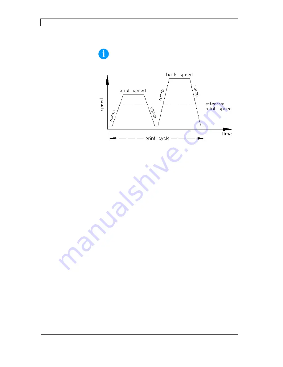
14.7  Cycle optimisation* 


NOTICE! 

The cycle is a finished print cycle per a unit of time. 


Figure 35 


In case of 'time critical' applications you have the possibility with a 
good selection of different device parameters to increase the effective 
print speed and it this way the clock cycle. 


Generally increase the print speed. 


Generally increase the back speed. 


Increase acceleration and brake ramp. 


Change zero point of machine. 


Avoid vertical installation position of print mechanics. Install the 
machine in horizontal position. 


Control the short distance between printhead and print surface. 


Switch off foil saving automatic. 


Optimise the layout to a short print way, i.e. less blanks, no 
borders at the top res. bottom, rotate the layout. 


*

 intermittent mode 

Содержание Dynacode IP Series

Страница 1: ......

Страница 2: ...evice can occur Please check www carl valentin de for the latest update Trademarks All named brands or trademarks are registered brands or registered trademarks of their respective owners and may not be separately labelled It must not be concluded from the missing labelling that it is not a registered brand or a registered trademark Carl Valentin direct print modules comply with the following safe...

Страница 3: ...7 8 Installation and Initial Operation 29 8 1 Installation of Print Mechanics at Machines 30 8 2 Required Space for Cable Outgoing 31 8 3 Connection of Pneumatic Power Supply 32 8 4 Adjustment of Pressure Power 33 8 5 Connecting the direct print module 34 8 6 Before initial operation 34 8 7 Print Control 35 8 8 Initial Operation 35 9 Loading the Transfer Ribbon Cassette 37 9 1 Transfer ribbon with...

Страница 4: ...Update 84 13 8 Filter 84 14 Maintenance and Cleaning 85 14 1 General Cleaning 85 14 2 Cleaning the Transfer Ribbon Roller 86 14 3 Cleaning the Printhead 86 14 4 Replacing the Printhead 87 14 5 Angle adjustment 88 14 6 Print Quality Optimisation 89 14 7 Cycle optimisation 90 15 Signal Diagrams 91 15 1 Continuous Mode 91 15 2 Intermittent Mode 95 16 Error correction 97 17 Additional Information 109 ...

Страница 5: ... print module is a state of the art device which complies with the recognized safety related rules and regulations Despite this a danger to life and limb of the user or third parties could arise and the direct print module or other property could be damaged while operating the device The direct print module may only be used while in proper working order and for the intended purpose Users must be s...

Страница 6: ...ilar personal items do not contact the exposed rotating parts NOTICE With the open printing unit due to construction the requirements of EN60950 1 regarding fire protection casing are not fulfilled These must be ensured by the installation into the end device The print unit can get hot during printing Do not touch the printhead during operation Cool down the print unit before changing material rem...

Страница 7: ...actured after 13 August 2005 As a principle this old equipment may not be delivered to communal collecting points It may only be organised used and disposed of by the manufacturer Valentin products accordingly labelled can therefore be returned to Carl Valentin GmbH This way you can be sure your old equipment will be disposed of correctly Carl Valentin GmbH thereby fulfils all obligations regardin...

Страница 8: ......

Страница 9: ...nt font types It can be printed inverse in italic format or 90 degrees turned fonts The handling of our durable direct print modules is easy and comfortable The parameter settings are made with the keys of the foil keyboard At each time the graphic display shows the current status By a new developed electronics a maximum print speed of up to 800 mm s continuous mode and 600 mm s intermittent mode ...

Страница 10: ...2 12 Connecting cable SPI printhead sensor 13 Connecting cable Power 14 Switch 15 Power cable with safety plug and strain relief 16 External inputs outputs 17 Connection encoder and product sensor 18 Connection encoder and product sensor 19 Alarm output relais 10 Ethernet interface 10 100 11 USB host for USB keyboard and USB memory stick ...

Страница 11: ...y the encoder It is only possible to print when respecting the operating conditions i e the speed has to be observed 3 2 Print Principle Figure 3 After starting a print order the printhead moves against the print medium The feed of material is registered by the encoder and then evaluated The printhead is in start position as long as the printing onto the moving material is finished and then it mov...

Страница 12: ... 3 3 Material Guiding Figure 4 NOTICE In case the encoder is connected to the counter pressure roll or the encoder roll you have to observe that the material has sufficient adhesion at the pressure roll or encoder roll to guarantee an exact speed by the encoder ...

Страница 13: ... to be printed After the print procedure the printhead again lifts up and the printing carriage moves again to the starting position 4 2 Print Position NOTICE The direct print module is delivered with a default print length of 65 mm In order to use the maximum print length of 75 mm the print position value must be changed to 93 see chapter 12 5 Maschinen Parameter intermittierender Modus page 56 F...

Страница 14: ......

Страница 15: ... regularly Content of the training are chapter 5 Operating Conditions chapter 9 Loading the Transfer Ribbon Cassette and chapter 14 Maintenance and Cleaning These indications are also valid for someone else s equipment supplied by us Only use original spare and exchange parts Please contact the manufacturer with respect to spare wear parts The installation place of direct print module should be ev...

Страница 16: ...000 6 3 01 2007 Interference voltage to wires according to EN 55022 05 2008 Interference field power according to EN 55022 05 2008 System perturbation according to EN 61000 3 2 09 2005 Flicker according to EN 61000 3 3 05 2002 Immunity according to EN 61000 6 2 03 2006 Stray radiation against discharge of static electricity according to 61000 4 2 03 2009 Electromagnetic fields according to EN 6100...

Страница 17: ...nector housings Shielded cables and connectors are necessary in order to avoid radiant emittance and receipt of electrical disturbances Allowable lines Shielded line 4 x 2 x 0 14 mm 4 x 2 x AWG 26 6 x 2 x 0 14 mm 6 x 2 x AWG 26 12 x 2 x 0 14 mm 12 x 2 x AWG 26 Sending and receiving lines have to be twisted in pairs Maximum cable length interface V 24 RS 232C 3 m with shielding USB 3 m Ethernet 100...

Страница 18: ... the direct print modules Control the correct handling of our products and repeat training We do not guarantee that all features described in this manual exist in all models Caused by our efforts to continue further development and improvement technical data might change without notice By further developments or regulations of the country illustrations and examples shown in the manual can be diffe...

Страница 19: ... mm 110 mm 130 mm Dimensions in mm width x height x depth Print mechanics without mounting frame 204 x 182 x 235 204 x 182 x 290 204 x 182 x 310 with mounting frame depending on passage width Control unit 310 x 165 x 350 connecting cable set to the mechanics 2 5 m Weight Print mechanics 9 5 kg 11 kg 11 7 kg Electronics with cable 8 kg 8 kg 8 kg Electronics Processor High Speed 32 Bit RAM 16 MB Slo...

Страница 20: ...d height 0 8 5 6 zoom 2 9 orientation 0 90 180 270 Vektor fonts TrueType fonts size in width and height 1 99 mm variable zoom orientation 0 90 180 270 Font attributes depending on character font bold Italic inverse vertical Font width variable Bar codes 1D bar codes CODABAR Code 128 Code 2 5 interleaved Code 39 Code 39 extended Code 93 EAN 13 EAN 8 EAN ADD ON GS1 128 Identcode ITF 14 Leitcode Phar...

Страница 21: ...uct sensor PS Print start CON3 D Externe I O 7 1 Alarm output Port 13 CON1 With the alarm output the device makes available the changeover contact of a relay The relay can be used either as Normally Closed Contact or as Normally Open Contact Figure 8 Pin Description 1 NO normally open contact 2 C centre contact 3 NC normally closed contact 4 PE 5 Not occupied 6 Not occupied Load current 1 A Contac...

Страница 22: ... 3 Encoder lane A 4 UB external max 30 VDC 5 UB internal approx 24 VDC 6 Input product sensor PS Print start Port 1 7 Encoder lane B Casing Shielding Max load current 100 mA NOTICE Pin 1 and Pin 2 must be bypassed if the encoder and or product sensor should be operated with the voltage supply of the control unit See connection examples page 24 and 25 ...

Страница 23: ...3 7 IN3 Reset counter 4 12 IN4 X 5 Not existing 6 Not existing 7 Not existing 8 Not existing 9 4 OUT1 Error message 10 6 OUT2 Print order 11 8 OUT3 Generation 12 10 OUT4 Printing 13 13 OUT5 Device ready signal 14 14 OUT6 Error 15 15 not occupied 16 16 not occupied Housing Shielding NOTICE OUT5 Port 13 controls internally still a relay alarm output 6 pin plug Max Load current 100 mA ...

Страница 24: ...relais with internal power supply x 4 x 5 x 6 x 1 x 2 x 4 x 5 x 6 x 1 x 2 CON2 Potential free or electronical relais Connector CON2 PS encoder Product sensor 7 pin DC coupled Ub external Ub internal PS input GND internal GND external Prod sensor Prod sensor J2 is to be inserted into 2 3 default Potential free or electronical relais Figure 12 Encoder connection with internal power supply Connector ...

Страница 25: ... with external power supply DC isolated x 4 x 5 x 6 x 1 x 2 NPN 1 Ub external 24VDC 10 GND external Connector CON2 PS encoder Product sensor 7 pin Ub external Ub internal PS input GND internal GND external Prod sensor J2 is to be inserted into 2 3 default Figure 15 PS connection PNP push pull with external power supply DC isolated x 4 x 5 x 6 x 1 x 2 Ub external 24VDC 10 GND external PNP 2 Connect...

Страница 26: ...7 brown green brown green white green Figure 17 x 11 x x 1 PS connection with external power supply Connector CON3 I O I O 16 pin Ub ext OUT PS input GND ext Potential free or electronical relais Prod sensor PS DC isolated With external power supply jumper 1 1 2 3 4 5 6 default may not be inserted Ub external 24VDC 10 GND external 2 Figure 18 Connection alarm relay Connection alarm relay Currentle...

Страница 27: ...put Error 15 Output Return 16 Output Transfer ribbon prior warning Port Function 11 Input Print start 12 Input Error reset 13 Input Number of the file to load Bit 0 Input 14 Input Number of the file to load Bit 1 Input 15 Input Number of the file to load Bit 2 Input 16 Input Number of the file to load Bit 3 Input 17 Input Number of the file to load Bit 4 Input 18 Input Number of the file to load B...

Страница 28: ... Ready 14 Output Error 15 Output Return 16 Output Transfer ribbon prior warning Port Function 11 Input Print start 12 Input Reset error 13 Input Counter reset 14 Input No function 15 Input No function 16 Input No function 17 Input No function 18 Input No function 19 Output Error 10 Output Active print order 11 Output Generation 12 Output Printing 13 Output Print Ready 14 Output Printhead down 15 O...

Страница 29: ...near the printhead Check delivery for completeness Print mechanics Control unit with cable Cleaning cassette Connecting cable Mini controller Manometer Pneumatic tube Push on connector I O accessories mating connector for I Os Covers for not used connections 1 transfer ribbon roll Empty core mounted on transfer ribbon rewinder Cleaning foil for printhead Documentation CD with printer drivers NOTIC...

Страница 30: ...ssible due to the sealing strip at the bottom of the print mechanics otherwise the counter pressure plate or pressure roller can touch the print mechanics The best print results can be received if the silicon of the pressure roll consists of a hardness of approx 40 to 50 Shore A and or the elastometer of the counter pressure plate shows a hardness of approx 60 5 Shore A average value of roughness ...

Страница 31: ...Dynacode IP Series Installation and Initial Operation 08 16 Operating Manual 31 8 2 Required Space for Cable Outgoing Figure 21 Figure 22 Standard Cable outgoing sideways Option Cable outgoing behind ...

Страница 32: ...sary to make a connection between the pressure regulator and the print mechanics via a pneumatic tube Ø 8 mm Please observe the following notes Position pressure regulator as near as possible to the print mechanics The pressure regulator is only to operate in the direction that is indicated on its underside The direction shows the way of the streaming air It is not allowed to bend the pneumatic tu...

Страница 33: ...ure regulator The values are indicated in the following table NOTICE If the pressure power is set too low then the printhead has no more contact to the counter pressure plate This damages the printhead due to the missing heat dissipation during the printout In case of too low pressure an error message appears This error message is to protect the printhead for overheating only and is not to use as ...

Страница 34: ...ctrical outlet NOTICE Insufficient or missing grounding can cause faults during operation Ensure that all computers and connection cables connected to the direct print module are grounded Connect direct print module to computer or network with a suitable cable 8 6 Before initial operation Mount print mechanics Connect all cables between print mechanics and control unit Protect cables against unint...

Страница 35: ...rol input It is necessary for the control unit to recognise the moment of setting the start signal and therefore it is possible and also necessary to observe the print status by the outputs 8 8 Initial Operation Once all connections have been made Switch on the control unit After switching on the device the main menu appears which shows the model type current date and time Insert ribbon cassette s...

Страница 36: ......

Страница 37: ...fluid thoroughly with running water If the irritation persists consult a doctor Ensure good ventilation 9 1 Transfer ribbon with coating outside Figure 24 Turn the lever A 90 in clockwise direction Remove the ribbon cassette from the print mechanics by pulling handle B Load a new ribbon roll as far as it will go onto the unwinding roll C Load an empty cardboard roll as far as it will go onto the r...

Страница 38: ...cardboard roll as far as it will go onto the rewinding unit D Insert the ribbon according to illustration Fix the ribbon with an adhesive tape at the empty roll and tighten it by some turns of the core Push the ribbon cassette again onto print mechanics and take care that the ribbon not rip Turn the lever A 90 anticlockwise NOTICE The above illustration shows a left hand printing system If you are...

Страница 39: ...not sufficient in order to position the rolls surely and to protect it against rotating When using transfer ribbons with plastic cores a safe positioning of the roles cannot be ensured CAUTION Slippage of transfer ribbon roll placed on the rewinding unwind unit or the empty cardboard core leads to malfunctions When using transfer ribbon rolls with plastic cores the groove must be shimmed Remove sc...

Страница 40: ......

Страница 41: ...ng to the conditions during the operation of direct print modules of this construction type the print mechanics cannot be protected at the time of printing completely from ingress of water However it is possibly by means of the special Cleaning Cassette contained in delivery to protect the print mechanics according to the degree of protection of enclosure IP65 during standstill times of machinery ...

Страница 42: ... and dust The pneumatic tube and the connection cables to the control unit with the waterproof housings may not be removed Indications for maintenance and cleaning are described in chapter 14 page 85 Before the resumption of printing the cleaning cassette must be changed again with the transfer ribbon cassette CAUTION The direct print module can be damaged by ingress of water due to incorrect oper...

Страница 43: ...ing mode release of start signal Confirm settings and modifications Stop and continue current print orders Delete a stopped print order with key No further layout of the print order is printed Return to the previous input field Press keys and to change the values Skip to the next input field Press keys and to change the values In function menu increase figure at the cursor position In main menu up...

Страница 44: ...ailable Symbol Mode 0 Standard starting with figures M Starting with capital letters m Starting with small letters A Input Alt a Input Alt is switched off after one character This mode is displayed as default At first the figure which corresponds to the key is displayed then all capital and afterwards the small letters At first all capital then the small letters and at last the corresponding figur...

Страница 45: ...k Select the entry mode Confirm the entry and change to the main menu Confirm and or finish the entry Cursor moves one position to the left Cursor moves one position to the right Customized variables user guiding Change between the individual entries Customized variables user guiding Change between the individual entries C Delete the complete input The input is deleted only if before entered by us...

Страница 46: ......

Страница 47: ...ettings Operating mode Print offset Print position Layouts cycle Material speed control Machine Parameters Encoder resolution Material feed Material speed Print length Column printing Material selection Flip layout Rotate layout Alignment Layout Settings Operating mode Ribbon Save Speed Transferband ribbon correction Distance Number of cycles Expert parameters ...

Страница 48: ...fter measuring Device Settings Layout confirmation Standard layout Keyboard layout IN signal level OUT signal level Debounce Not ready error I O profile I O Parameters IP ddress Net mask Standard gateway Geschwindigkeit duplex DHCP Printer name Network MAC address Port Interval Remote Console COM1 Baud Parity Data bits Stop bit Interface Start sign Stop sign Data memory Port test ...

Страница 49: ... Date End of summertime Time Time shifting Date Time Photocell parameters Paper counter Heater resistance Printhead temperature Transfer ribbon length Transfer ribbon winding Brake Print examples Service Functions Encoder average Output Input Online Offline Diagnostic counter Warning diameter Transfer ribbon prior warning Load layout Change directory Load file Save layout Save configuration Delete...

Страница 50: ...cycle Maschine Parameters Back speed Print length Column printing Material selection Flip layout Rotate layout Alignment Layout Settings Operating mode Ribbon Save Transfer ribbon correction Expert parameters Field handling Codepage External parameters Buzzer Display Language Customized entry Hotstart Password protection Print after measuring Device Settings Layout confirmation Standard layout Key...

Страница 51: ...ror I O profile I O Parameters Start signal delay IP ddress Net mask Standard gateway Geschwindigkeit duplex DHCP Printer name Network MAC address Port Interval Remote Console COM1 Baud Parity Data bits Stop bit Interface Start sign Stop sign Data memory Port test Protocol Printhead resolution Drive mapping Emulation ...

Страница 52: ...Time Time shifting Date Time Photocell parameters Paper counter Heater resistance Printhead temperature Transfer ribbon length Transfer ribbon winding Brake Print examples Service Functions Diagnostic Output Input Online Offline Diagnostic counter Warning diameter Transfer ribbon prior warning Load layout Change directory Load file Save layout Save configuration Delete file Formatting CF Card USB ...

Страница 53: ...tion if the transfer ribbon roll is to end or if the ribbon was torn at the unwinding roll Off The ribbon control is deselected i e the direct print module continues without an error message On The ribbon control is selected i e the current print order is interrupted and an error message appears at the display Strong sensibility The direct print module reacts immediately to the end of the transfer...

Страница 54: ...ntered at print start is printed level evaluation of print start signal IO ST F IO static continuous Corresponds to IO static Continuous means that not only a defined number of pieces is processed but the same layout is printed as long as new data is transferred by interface IO DY IO dynamic The external signal is evaluated dynamically i e in case the direct print module is in waiting mode a singl...

Страница 55: ...arrive the next menu item Indication of number of printed layouts per print start cycle Value range 1 25 Figure 31 Press key to arrive the next menu item Check material speed at print start signal Off Default Material speed is only checked if the set offset value is taken into consideration It is possible to activate print start signal although the material is not yet in move However until the end...

Страница 56: ...rred After the generating process the target number and the actual number of pieces is shown in the display A cycle is started via signal input 1 or with key With each cycle the actual number of pieces is increased by the number of printed layouts In case the target number of pieces is reached the print order is finished and the display shows again the main menu Continuous mode A print order is tr...

Страница 57: ...in this way the life of the printhead Because of the mass moment of inertia it could be better to reduce the speed at an installation position of the print unit at 30 horizontal Value range 50 600 mm s Press key to arrive the next menu item Indication of distance of the layout res the first layout in case more layouts per cycles are to be printed to the zero point of machine Value range 0 93 mm De...

Страница 58: ...ut If the layout width was not transferred to the module automatically the default layout width i e the width of the printhead is used Because of this reason you have to note that the layout should have the same width as the printhead as otherwise this could lead to problems in positioning Press key to arrive the next menu item As default the layout is printed with 0 head forward In case of an act...

Страница 59: ...be achieved see chapter 18 3 page 119 SaveStrt No start signal loss direct print module regulates the ribbon save quality automatically according to requirement Automatic layout ribbon save and field ribbon save each without feedback see chapter 18 4 page 122 Determination of max print speed On the base of this value all necessary calculations e g feedback distance and smallest possible print offs...

Страница 60: ...aving Standard Maximum ribbon save performance i e with this setting there is no loss of transfer ribbon apart from the safety distance of 1 mm so the print fields are not printed one into the other No settings are allowed with which the ribbon save no more cannot be achieved This particularly applies for the print offset which can only be adjusted now in the valid range see chapter 18 5 page 123 ...

Страница 61: ... module The following possibilities are available ANSI character set Codepage 437 Codepage 850 GEM German GEM English GEM French GEM Swedish GEM Danish Press key to arrive the next menu item Layout dimension only The parameters for layout length gap length and layout width can be transferred to the printing system All other parameter settings are to be made directly at the printing system On Sendi...

Страница 62: ...cannot work with them There are several applications in which the use of password protection makes sense see chapter 17 3 page 112 Press key to arrive the next menu item On A new print order is only printed after confirmation at the device An already active continuing print order is printed as long as the confirmation is effected at the device Off No query appears at the display of control unit Pr...

Страница 63: ...w 0 s status can be affected by interface Press key to arrive the next menu item Indication of debounce time of the dispenser input The setting range of the debounce time is between 0 and 100 ms In case the start signal is not clear then you can debounce the input by means of this menu item Press key to arrive the next menu item Indication in time per second of the delay for the start signal Value...

Страница 64: ...r warning Output 1 Print start Input 2 Error confirmation Input 3 Number of the file to load Bit 0 Input 4 Number of the file to load Bit 1 Input 5 Number of the file to load 2 Input 6 Number of the file to load 3 Input 7 Number of the file to load 4 Input 8 Number of the file to load 5 Input 9 Error Output 10 No function 11 No function 12 No function 13 Ready Output 14 No function 15 Backfeed 16 ...

Страница 65: ... as long as you arrive the Network menu Press key to select the menu For more information please see the separate manual 12 12 Remote console Switch on the direct print module and the display shows the main menu Press key to access the function menu Press key as long as you arrive the Remote console menu Press key to select the menu For more information please contact our sales department ...

Страница 66: ...on of stop bits between bytes Value range 1 or 2 stop bits Press key to arrive the next menu item SOH Start of data transfer block Hex format 01 ETB End of data transfer block Hex formal 17 Two different start en signs can be set The settings are normally SOH 01 HEX and ETB 17 HEX Several host computers cannot process these signs and therefore SOH 5E HEX and ETB 5F cannot be set Press key to arriv...

Страница 67: ...item At activated ZPL II emulation the printhead resolution of the emulated direct print module must be set e g 11 8 Dot mm 300 dpi NOTICE If the printhead resolution of the Zebra printer differs from that of the Valentin device then the size of objects e g texts graphics complies not exactly Press key to arrive the next menu item The access to Zebra drives B CF card R RAM Disk standard drive if n...

Страница 68: ... This entry refers to the previously selected format Example summertime is automatically adjusted at last Sunday in March 03 Press key to arrive the next menu item By means of this function you can define the time when you want to start summertime Press key to arrive the next menu item Select the format in which you want to define end of summertime The example above indicates the default setting E...

Страница 69: ... R1 Transfer ribbon rewinding roll Indication of transfer ribbon rewinding roll status 4 states are indicated no marking in photocell marking from right marking from left marking completely in photocell R2 Transfer ribbon unwinding roll Indication of transfer ribbon unwinding roll status 4 states are indicated no marking in photocell marking from right marking from left marking completely in photo...

Страница 70: ...rrive the next menu item Settings Printout of all settings such as speed and transfer ribbon material Bar codes Printout of all available bar code types Fonts Printout of all available font types Press key to arrive the next menu item Indication of level for inputs of the IO parameters 0 Low 1 High Press key to arrive the next menu item Indication of the level for outputs of the IO parameters 0 Lo...

Страница 71: ...ng the device prints is active MS I Manual stopped interrupted Stop key onto foil keyboard panel or in a program was pressed ItfI Interface interrupted The print order was cancelled because new data was received by an interface SpedS Speed stopped The print order was cancelled because the measured print speed was too slow Press key to arrive the next menu item This function is activated e g if the...

Страница 72: ...re the end of transfer ribbon a signal is send by the control output Setting of transfer ribbon advance warning diameter In case you enter a value in mm then a signal appears via control output when reaching this diameter measured at transfer ribbon roll Transfer ribbon advance warning Warning diameter ...

Страница 73: ...ve print order The display shows the following Press key key to continue the interrupted print order In case an active print order was interrupted by means of key and afterwards key pressed then the print order was cancelled and the direct print module changes to the main menu During the print order the number of layouts which already printed is indicated Press the key to change to the menu item m...

Страница 74: ......

Страница 75: ...dium it is recommend to copy the most important data by means of a commercial Card Reader 13 2 Display Structure Load layout A STANDARD File_name1 prn File_name2 prn File_name3 prn File_name4 prn 1 Current function 2 2 lined header 3 Scroll range 4 File names directory names 5 Marking of the selected file cursor 6 Current path drive directory The two line header 2 contains the current function nam...

Страница 76: ...he previous menu Function Load layout Change to the File Explorer File Explorer Change to the context menu Select a file directory if a multiple selection is possible Main menu Access to the memory menu File Explorer Create a new file Start the current function for the active file directory Change to the superordinate directory Change to the currently marked directory In the current directory scro...

Страница 77: ...ing of CF card is effected at PC and thus the STANDARD directory was not created automatically The user directory is the root directory in which the user saves usually the most frequently used files layouts The utilisation of the user directory permits the quick and direct access to the files saved in the defined user directory The definition of an user directory saves thus a long search of the fi...

Страница 78: ...yed as user directory 13 5 Load Layout Loads a layout within a defined user directory The function allows quick access to the desired layout as only layout files are displayed and directories hidden Press key to access to the memory menu Press keys to select the layout to be printed Press key to confirm the selection The printer display shows automatically the window to insert the number of copies...

Страница 79: ...ory press key to access to the File Explorer Following functions are available Change drive and or directory Load file Save layout and or configuration Delete file s Format CF card Copy file s Selection of drive and or directory in which the files are saved Press key to access to the memory menu Press key to call the File Explorer Press keys to select the directory Press key to confirm the selecti...

Страница 80: ... key to load the selected file If the selected file is a layout then the number of copies to print can be entered immediately Saves the currently loaded layout under the selected name Press key to access to the memory menu Press key to call the File Explorer Press key to change to the menu Save file Selct the function Savel layout and confirm the selection with key If an USB keyboard is attached a...

Страница 81: ...signed Deletes one or more files and or directories irrevocably With the deletion of a directory both the contained files and the subdirectories are deleted Press key to access to the memory menu Press key to call the File Explorer Press keys and to select the file Press key to mark the files which are to be deleted The marked entries are listed with Repeat this procedure until all desired files a...

Страница 82: ...emory card NOTICE USB sticks cannot be formatted at the printer Press key to access to the memory menu Press key to call the File Explorer Select the drive which is to format with the navigation keys Press key to call the context menu Select the function Format and confirm the selection with key Formatting ...

Страница 83: ... Press key to call the File Explorer Press keys and to select the file Press key to mark the files which are to be copied The marked entries are listed with Repeat this procedure until all desired files and or directories are marked for copying Press key to call the context menu Select the function Copy and confirm the selection with key Select the target storage with the navigation keys and press...

Страница 84: ...e prn is selected loaded In the first step the printer executes the firmware update After the necessary restart automatically the file data prn is loaded In this way the remaining components were updated is After a renewed restart the update procedure is finished 13 8 Filter For certain functions a filter mask or a file name of a file which is to be saved can be entered This input is indicated in ...

Страница 85: ...eaning printhead see chapter 14 3 page 85 Each time the transfer ribbon is changed or when the printout is adversely affected Replacing printhead see chapter 14 4 page 87 In case of errors in printout NOTICE The handling instructions for the use of Isopropanol IPA must be observed In the case of skin or eye contact immediately wash off the fluid thoroughly with running water If the irritation pers...

Страница 86: ... Printing can cause accumulation of dirt at printhead e g by colour particles of transfer ribbon and therefore it is necessary to clean the printhead in regular periods depending on operating hours environmental effects such as dust etc CAUTION Printhead can be damaged Do not use sharp or hard objects to clean the printhead Do not touch protective glass layer of the printhead 1 Remove transfer rib...

Страница 87: ...be inserted in the screws A 4 Remove screws A and afterwards the printhead B 5 Remove rear mounted connection assembly from printhead 1 Insert connection assembly to the new printhead 2 Position printhead in printhead support C so the engaging pieces catch in the appropriate holes in the printhead B 3 Hold printhead holder C with a finger slightly on the pressure roll and check the correct positio...

Страница 88: ... Higher wastage of ribbon by faster ripping Change factory settings only in exceptional cases 1 Loosen slightly two Allen head screws A 2 Move adjusting part B to adjust the angle between printhead and printhead support move downwards decrease angle move upwards increase angle 3 Tighten again the Allen head screws A 4 Start a print order with approx 3 layouts to check the correct unwrinkled ribbon...

Страница 89: ...rior print quality Increase contrast Increase pressure Reduce print speed Reduce transfer ribbon speed Reduce distance between printhead and print surface Change combination of transfer ribbon and print medium Control print surface too soft Change print angle Partial inferior print quality on one side Align surface parallel to printhead Set regular transfer ribbon tension Set regular printhead ang...

Страница 90: ...tive print speed and it this way the clock cycle Generally increase the print speed Generally increase the back speed Increase acceleration and brake ramp Change zero point of machine Avoid vertical installation position of print mechanics Install the machine in horizontal position Control the short distance between printhead and print surface Switch off foil saving automatic Optimise the layout t...

Страница 91: ... and a print order is only finished after the feed of the complete layout the smallest possible time between two start impulses depends also from the layout length In case the printable data is only at the beginning of the layout and the rest of the layout is empty then it is possible to decrease the time of start impulse by minimising the layout length not for data memory extended As soon as the ...

Страница 92: ...he direct print module has no further action At receipt of the following layout the time of receipt is longer because the direct print module receives data and prints at the same time In mode data memory extended already received data is always generated after the start of a print order Before the current print order is finished the next one is already generated The signal output is therefore acti...

Страница 93: ... are to print are the same and therefore it is only necessary to generate the layout once Because only 1 print order is send the direct print module has only to receive once As the print order consists of 3 layouts the print order output is active as long as all 3 layouts are printed In dispensing mode dynamic only the slope of the start impulse is recognised as valid print start signal However th...

Страница 94: ...r In dispensing mode static the level of the start impulse is recognised as valid start signal In case the level is activated then the print is continued immediately if the following layout is already generated After deleting the signal the machine prints until the end of the current layout and then the direct print module waits for the next start impulse Dispensing Mode Static Layout Print start ...

Страница 95: ...Dynacode IP Series Signal Diagrams 08 16 Operating Manual 95 15 2 Intermittent Mode Mode 1 single item processing Mode 2 continuous mode ...

Страница 96: ...Signal Diagrams Dynacode IP Series 96 Operating Manual 08 16 Mode 4 continuous mode return without layout printing signal ...

Страница 97: ...not available Check font 7 Vector font Selected font is not available Check font 8 Measuring label While measuring no label was found Set label length is too large Check label length and if labels are inserted correctly Restart measuring anew 9 No label found No label available Soiled label photocell Labels not inserted correctly Insert new label roll Check if labels are inserted correctly Clean t...

Страница 98: ...e entered res received check digit is wrong Calculate check digit anew Check code data 21 Invalid SC number Selected SC factor is invalid for EAN res UPC Check SC factor 22 Invalid number of digits Entered digits for EAN res UPC are invalid 12 13 Check number of digits 23 Check digit calculation Selected check digit calculation is not available in the bar code Check calculation of check digit Chec...

Страница 99: ...he printhead and start print order anew 36 BCD invalid format BCD error Invalid format for the calculation of Euro variable Check entered format 37 BCD overflow BCD error Invalid format for the calculation of Euro variable Check entered format 38 BCD division BCD error Invalid format for the calculation of Euro variable Check entered format 39 FLASH ERROR Flash component error Run a software updat...

Страница 100: ...longer required files 54 File directory exists The selected file directory already exists Check name select a different name 55 File too large During copying procedure not enough memory space onto target drive available Use a larger target card 56 No update file Errors in update file of firmware Start update file anew 57 Invalid graphic file The selected file does not contain graphic data Check fi...

Страница 101: ...ange printhead 71 Invalid page As page number either 0 or a number 9 is selected Select a number between 1 and 9 72 Page selection A page which is not available is selected Check the defined pages 73 Page not defined The page is not defined Check the print definition 74 Format user guiding Wrong format for customised entry Check the format string 75 Format date time Wrong format for date time Chec...

Страница 102: ... or use an offset 88 RFID verify Error while checking programmed data Faulty RFID label Check RFID definitions 89 RFID timeout Error at programming the RFID label Label positioning Faulty label 90 RFID data Faulty or incomplete definition of RFID data Check RFID data definitions 91 RFID tag type Definition of label data does not correspond with the used label Check storage partitioning of used lab...

Страница 103: ... down is missing option APL 100 Check input signals compressed air supply 102 Vacuum plate empty Sensor does not recognise a label at vacuum plate option APL 100 Check input signals compressed air supply 103 Start signal Print order is active but device not ready to process it Check start signal 104 No print data Print data outside the defined label Selection of wrong module type design software C...

Страница 104: ...matics for cross traverse 116 Print position The print position is not correct Check TOP and RIGHT final position switch for correct function and position Check pneumatics for function 117 XML parameter The parameters in the XML file are not correct Please contact your responsible distributor 118 Invalid variable Transferred variable is invalid with customized entry Select correct variable without...

Страница 105: ...The settings of the photocell are not correct Check label photocell settings Settings of label size and gap size are not correct Check correct loading of label material No label found at the rear printhead Insert new label roll Soiled label photocell Clean the label photocell Labels not inserted correctly Check if labels are inserted correctly 124 Speed too slow The print speed is too slow Increas...

Страница 106: ......

Страница 107: ... with the largest x coordinate i e it has the largest distance to the printhead Press key to access the function menu Press key as long as you arrive the menu Label layout Press key to confirm the selection Press key as long as to the menu item Width Columns Press keys and to set the layout width The Width is the width of one column e g 20 0 mm Press keys and to arrive the Column input field Press...

Страница 108: ...he data of the current layout is saved to the corresponding directory of the CF card However the following conditions have to be fulfilled CF card inserted in drive A CF card not write protected Enough free storage space onto CF card An error message appears in case these conditions are not fulfilled At switching off the direct print module the state of the current print order is saved to the corr...

Страница 109: ...a customized entry was active during switching off the direct print module the window for the first customized variable is displayed As in the intended file only the start values of the counter are saved they are refreshed at a new start of the print order by means of the number of printed layouts Each counter is counted corresponding from its start value Afterwards the position of the current and...

Страница 110: ...sor blocks the entry of mask and the function menu By this means the user indeed can print layouts but the set up of direct print module and the masks of the layout cannot be changed To receive a most flexible password protection the device functions will be divided into several function groups In the function menu the print parameters can be changed contrast speed mode The password protection pre...

Страница 111: ...ur digit number possible values 0000 9999 has to be entered Now the modifications can be made The user can define the password in the first line four digit number Press key to continue Press keys and to activate deactivate Yes No the password protection Press key to change to the second line Press keys and to block open individual function groups Press keys and to change to the next group F Functi...

Страница 112: ......

Страница 113: ...ave and in this way of the print quality are to be connected with the available time which is needed for decelerating and accelerating of transfer ribbon There are two different types of ribbon save It is tried to save transfer ribbon with gaps within the layout Because of the fact that the gaps are usually very small only little time is available Therefore a feedback is not reasonable lack of tim...

Страница 114: ... optimal ribbon save is reached no loss of transfer ribbon This is rather rarely realised as the ribbon position can deviate because of inaccuracies at speed measurement encoder Default 1 mm xx mm The feedback can be made smaller It causes loss of transfer ribbon but the number of cycles is increased If the value is increased to the complete backfeed length then the direct print module sets automa...

Страница 115: ...his is used from ribbon save algorithm for the calculation of start time of printhead upwards movement REStartT ribbon motor early start time in ms This value is added to the increase time of transfer ribbon movement Time indication for the time between motor reached material speed and printhead burns If the same value is entered as for PhDownT the printhead upwards movement is not started before ...

Страница 116: ...ldRS field ribbon saving Off Field ribbon save mode Off PHOnly Only the printhead is moved The transfer ribbon is not stopped Normal Field ribbon save is executed only if the transfer ribbon motor is completely stopped Strong Field ribbon save is executed even if the transfer ribbon motor is not stopped Rwind v rewind speed in mm s Indication of rewind in mm s Press key to arrive the next menu ite...

Страница 117: ...the menu Press key and to select the ribbon save mode Shift Press key to arrive the first menu item X Shift Indication of displacement of the printout in X direction The printout can be displaced by the entry of a positive or negative value in both directions Y Shift Indication of displacement of the printout in printing direction Enter value 0 in order to achieve a print result in which the colum...

Страница 118: ...lane X Shift 2 mm Y Shift 3 mm Lanes 2 R Shift 5 X Shift 2 mm Y Shift 3 mm Lanes 2 R Shift 3 mm 13 06 2008 13 06 2008 13 06 2008 13 06 2008 13 06 2008 13 06 2008 2 4 2 X Shift Y Shift 13 06 2008 13 06 2008 13 06 2008 13 06 2008 13 06 2008 13 06 2008 2 X Shift 13 06 2008 13 06 2008 13 06 2008 13 06 2008 13 06 2008 13 06 2008 13 06 2008 13 06 2008 Print direction Lanes R Shift Example Layout Transfe...

Страница 119: ...d that the print speed is so high that no field ribbon save is possible but after a lane enough time is available then by means of the shift ribbon save the gap of the fields can be filled with suitable layouts Press key to arrive the next menu item This menu item is password protected Enter password press key to confirm the entry Please find the description of Expert Parameters in chapter 18 2 pa...

Страница 120: ...ss the function menu Press key as long as you arrive the Ribbon save menu Press key to select the menu Press key and to select the ribbon save mode SaveStrt Press key to arrive the first menu item This menu item is password protected Enter password and press key to confirm the input Please find the description of Expert Parameters in chapter 18 2 page 116 Ribbon save mode Expert parameters ...

Страница 121: ...of the printhead downwards movement PhUpT printhead up time in ms Is used from the ribbon save algorithm to calculate if a field ribbon save is possible or not Press key to arrive the next menu item PhVReactT valve reaction time in ms The time is calculated when the printhead upwards movement is started Press key to arrive the next menu item Tension Indication of length that is transported forward...

Страница 122: ...ess key and to select the ribbon save mode Shift Press key to arrive the first menu item Please find the description in chapter 18 3 page 119 Press key to arrive the next menu item Please find the description in chapter 18 3 page 119 Press key to arrive the next menu item This menu item is password protected Enter password an press key to confirm the input Please find the description of ExpertPara...

Страница 123: ...ad file 80 Load layout 78 Navigation 76 Save configuration 81 Save layout 80 Connection 34 Connection side of print mechanics 9 Connector assignment of control unit 10 Continuous mode Material guiding 12 Material speed 11 Print principle 11 D Display during printing 73 E Environmentally friendly disposal 7 Error messages corrections 105 Error messages Error corrections 97 98 99 100 101 102 103 104...

Страница 124: ... operation 35 Initial operation preparations 34 Inputs outputs 27 28 Inputs Outputs 21 Alarm output 21 Encoder 22 External power supply 25 26 I O assignment 23 Internal power supply 24 Product sensor 22 Installation at machines 30 Instructions 5 Intended use 5 Intermittent mode Print position 13 Print principle 13 K Keyboard Standard 43 Text entry User guiding 44 45 M Maintenance cleaning Angle ad...

Страница 125: ...ve 115 Continuous mode 116 117 118 119 120 121 122 Intermittent mode 123 124 S Safety instructions 6 7 Scope of delivery 29 Signal diagrams Continuous mode 91 92 93 94 Intermittent mode 95 96 T Technical data 19 20 Transfer ribbon loading Coating inside 38 Coating outside 37 U Unpacking 29 USB Stick Change directory 79 Copying 83 Delete file 81 Display structure 75 Filter 84 Firmware update 84 Loa...

Страница 126: ......

Отзывы: