14
8.
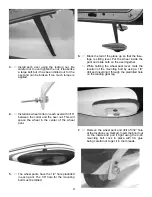
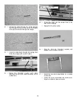
Pull the rudder cables to the servo and thread
a swage on each. Fit cable through hole in
threaded coupler and back through the swage.
Do both cables at the same time and pull both
tight before crimping swage. Make sure servo
is centered and rudder is centered. Pull both
cables tight and crimp swage.
Engine Installation
1.
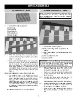
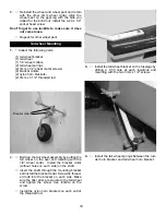
Collect the following items:
(2) Motor mounts
(4) 4 mm bolts
(4) 4mm blind nuts
(4) flat washers
(4) 3.5mm x18mm screws
2.
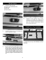
Draw a line across the firewall in the center.
Draw a line down the firewall offset 3/16” to the
left side of the plane. The 3/16” will compen-
sate for the 2 degrees of right thrust built into
the firewall. Note: The firewall will have a 1“
hole in the center not shown on the photo.
3.
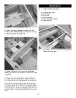
Clamp your motor between the beams of the
two mounts and set flat on the work bench.
Make sure the motor is square to the table and
both mounts sit flat.
Put a scrap piece of wood in the prop mount
and measure both sides to make sure it is
square. The distance from the table to the front
of the thrust washer (scrap wood ) will have to
be at least 6-1/4” to clear the front of the cowl.
If you cannot get this much by moving the
engine to the front of the mounts, you will have
to shim the mounts out. Our OS 1.20 fit all the
way to the end of the mounts.
4.
With the motor clamped in place, mark the
location of the mounting holes. Drill a 1/8” hole
and screw the motor in place using the 3.5mm
screws. Be careful and don’t over torque the
screws or they will break.

