8
5.
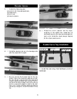
Install the other two hinges. Trial fit the eleva-
tors in place making sure they will fit tightly
against the trailing edge of the stab and work
smoothly.
When satisfied with the fit, remove elevator
and apply epoxy in the holes the same as with
the ailerons. Work the elevators up and down
several time and set aside to dry..
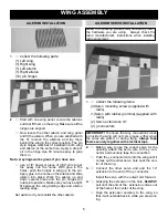
1.
Collect the following items:
(1) Rudder
(1) 6-32 x 4” threaded rod
(2) nylon ball washers
(2) nylon ball nuts
(2) nylon clevis assemblies
(2) nylon pushrod connectors
(3) Pin style hinges
1.
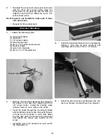
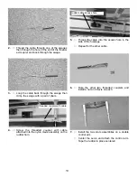
Insert the three hinges in the fin until the hinge
pin is on the hinge line. Fit the rudder in place
on the hinges.
2.
Locate the exit hole in the side of thefuselage
for the rudder pull-pull cable. Using a straight
edge, mark the location of the control horn on
the rudder in line with the hole
3.
Drill a 9/64” hole at the location you just
marked. Drill half way from each side as you
did on the ailerons.
1.
Collect the following items.
(2) Landing gear legs
(6) 6-32X3/4” Socket head screws
(6) #6 flat washers
(2) Wheel pants, one left one right
(2) 4mm axels with lock nuts
(4) 4mm wheel collars
(2) 3-1/4” wheels
(2) 4-40 x t-nuts
(2) 4-40 x 1/2” socket head bolts
2.
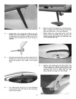
Slide gear leg into slot on side of fuselage and
install retaining bolts through the gear legs
from the inside of the fuselage.Be sure to use
thread lock on the bolts. The blind nut are
already installed.
Rudder Installation
4.
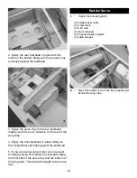
Install the 4” threaded rod with a ball washer
and ball nut on each side. Center the bolt in the
rudder. Install the nylon pushrod connector for
the tail wheel steering springs and then the
nylon clevis assemblies. Repeat for the other
side.
5.
Trial fit the rudder in place making sure the
hinge line is tight against the fin. When satis-
fied with the fit glue the hinges in place using
the same procedure you did with the ailerons.
Landing Gear Installation

