14
14
TRIM THE COWL
❏
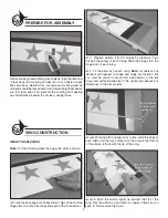
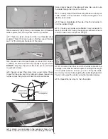
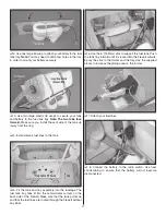
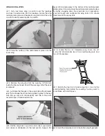
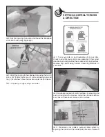
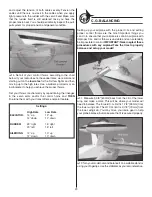
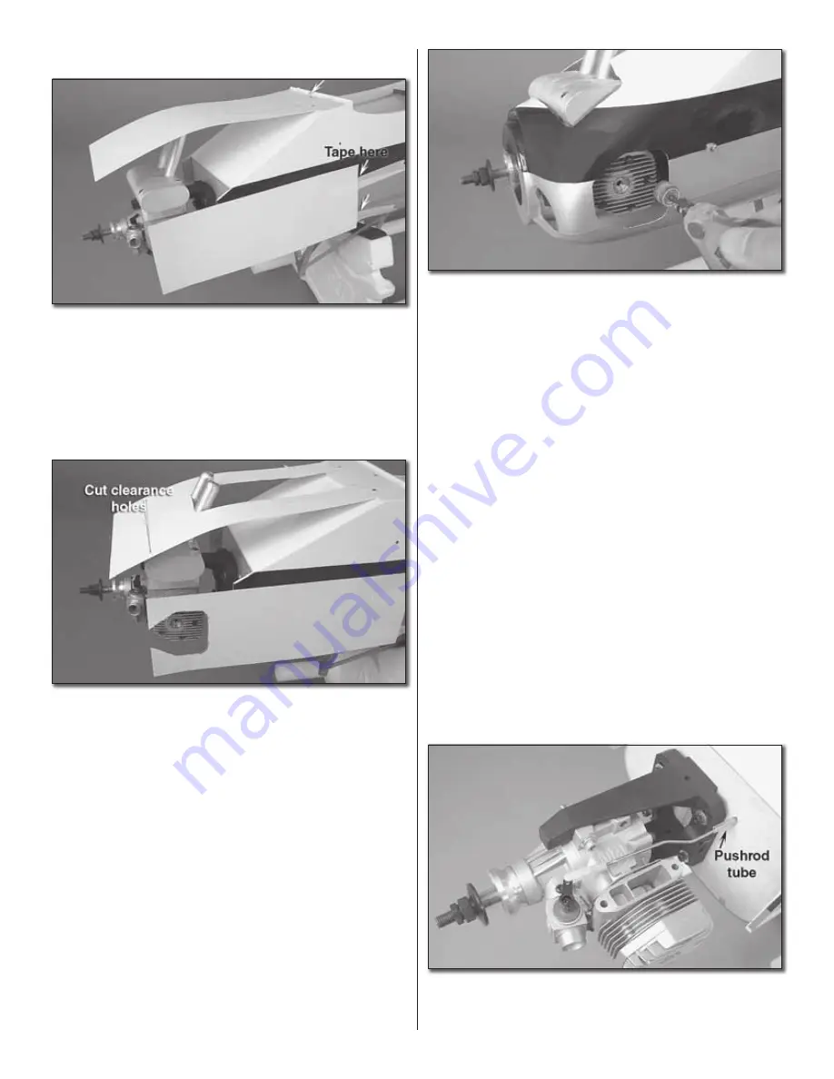
1. Tape a 4" x 13" [102 x 330mm] piece of card stock to the
fuselage so that it lays over the cylinder head. Tape a 6" x 11"
[152 x 280mm] piece of card stock to the fuselage bottom so
that it is positioned over the muffl er. You may also need to
make a template for your mixture control valves.
❏
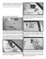
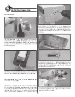
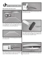
2. Trim a hole in the card stock to accommodate your
engine’s cylinder head, muffl er, and mixture control valves.
Trim a little and then check your progress by laying the
templates over the engine. When you’re satisfi ed, leave the
templates attached where they are. You’ll be fi tting the cowl
next, so the engine will be removed. The templates will help
you transfer your engine’s exact location to the outside of
the cowl.
❏
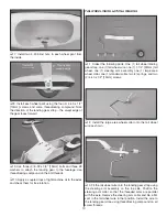
3. Remove the engine and engine mount and set them
aside. If your engine does not interfere with the cowl, you may
leave it attached. We left the engine attached and removed
the muffl er.
❏
4. Use the six (6) 1/2" [13mm] button head screws to
attach the cowl.
❏
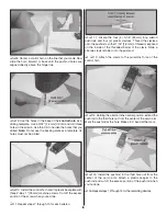
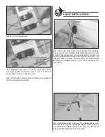
5. Trace around the openings in the templates you made.
Use a Dremel tool to cut a hole in the cowl for the cylinder
head, muffl er, and needle valves. Fit the engine and muffl er
and re-trim where necessary.
❏
6. Remove the cowl and set it aside.
THROTTLE PUSHROD & SERVO INSTALLATION
❏
1. Install your engine and engine mount using threadlocking
compound with the four (4) 8-32 x 1" [25mm] engine mount
bolts and four (4) #8 washers.
❏
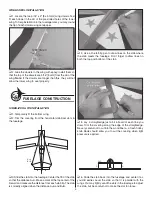
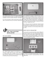
2. Locate the 20" [508mm] throttle pushrod, the throttle
pushrod tube, one threaded clevis, and one silicone clevis
retainer. Thread the clevis on so that at least 1/16" [1.6mm] is
threaded past the inside end of the barrel of the clevis.
❏
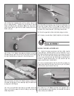
3. Fit the pushrod tube into the hole that you drilled earlier
and slide the pushrod into the tube. Attach the clevis to the
throttle arm. Bend the pushrod around any obstructions.


