11
Check which of the possible solutions is applicable to your automation project
and perform a few manual trials before fixing the brackets. If necessary use the
adjustable brackets
206/BLASR
.
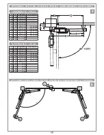
• Start by defining the position of the rear bracket by plotting the values in the tables
horizontally referred to
fig. 5.
For example: measuring dimension "
C
" (e.g. 90 mm)
makes it possible to calculate dimensions "
A
" (e.g.
160 mm
) and "
B
" (from
150 to
190 mm
); for other factors, consider that dimension "
B
" can vary by
+/- 20 mm
and dimension "
A
" can be modified by choosing a different hole in the bracket.
Attention: assess these tolerances well because the more dimensions "A"
and "B" are similar, the smoother the gate jeaf movement will be.
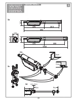
• The rear brackets are supplied in two parts (with non-welded plate) offering the
freedom to: shorten or tilt the bracket or fix the drilled bracket directly to the
gate post (
figs 4b, 4c
). For fixing with screw anchors and/or screws the bracket
must be welded to the plate as shown in
fig. 4b
. Even if the structure of
BLA24
is designed to adapt to imperfections or structural deterioration of the fixing, the
importance of using maximum precision when levelling the brackets (
fig. 4c
) cannot
be underestimated.
• The height of the brackets is established easily using a spirit level; the front bracket
must be
27 mm
lower (
fig. 4d
); in addition, calculate the final height of the actuator
such as to allow correct outlet of the electrical cables or choose a higher position
to reduce the accumulation of dirt, grit and moisture (
fig. 4e
).
• After having secured the rear bracket and marked the height of the front bracket
proceed as follows:
- secure the actuator as shown in
fig. 4f
;
- fix the front bracket to the actuator;
- move the gate leaf to its fully closed position;
- move the ram to its closed position (a few millimetres before max. extension);
- place the front bracket on the gate leaf and mark the holes.
• Before final fixing (screws or welding) perform a manual opening and closing
movement and check the ram is level (
fig. 4e
).
The
BLA24
Models feature an internal system for mechanical stroke limitation com-
posed of adjustable and independent stop rings (parts
11
and
14
in
fig. 2
), one for the
opening stroke and one for the closing stroke. To set the stop rings proceed as follows:
- remove the screws (part
6
,
fig. 2
) and remove the cover (part
4
,
fig. 2
).
- fit the mechanical stop to the lead screw (
fig. 3c
) while keeping the fixing screws
backed off.
- move the leaf towards the actuator maximum stroke limit and fully tighten the
screws of the mechanical stops
- perform an opening and closing cycle to check the stop rings are correctly posi-
tioned and then refit the actuator cover.
In order to guarantee the correct operation of the appliance you must
use a Cardin direct current electronic programmer available in the
following versions:
PRG900
for one or two motors.
Before connecting the appliance make sure that the voltage rated on the data
plate conforms to that of the mains supply.
• The appliance works off a
24V direct current power supply (see wiring
diagram).
• Do not use cables with aluminium conductors; do not solder the ends of cables
which are to be inserted into the binding posts; use flexible multiwire cable
2x1,5 which are marked
T min 85°C
and are resistant to atmospheric agents.
• The power cable must have enough slack to make sure it is not pulled tight
during normal operation.
• Insert a shunt box (fitted with cable clamps) near each motor.
• The power cable must not be wound around any of the appliances components
and must not be cemented into the wall.
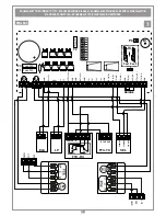
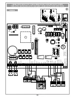
• Connect the power cable to the terminal board as shown in figure 7.
IMPORTANT!
The geared motor is not fitted with a torque limiter. Only use
an electronic programmer which has a torque limiter with maximum force at
the head of the gate equal to
150 N
(local standards and regulations in force).
SETTING THE MOTOR TORQUE (see control unit)
When carrying out the installation you are advised to use a Cardin control unit
fitted with a torque limiter.
The Cardin programmers optimise the correct working order of the "machine"
(motorised gates/doors) and guarantee full power maximum thrust at the start of the
opening/closing manoeuvre).
The programmer also guarantees that the effective torque fed to the system will be
that selected by the operator in the control unit. The choice of settings depends
on the weight and
size of the gate leaf/door and the different environmental
conditions on-site.
You are reminded that the standards and regulations in force unequivo-
cally require that the torque be set to a level suitable for the system.
Correctly choosing the torque will guarantee maximum security and long
life for the mechanical components.
ADJUSTING THE MECHANICAL TRAVEL LIMITS
MANUAL RELEASE AND LOCKING PROCEDURE
Prodotti TELCOMA
BLA24
20-10-2014
DI0621
Description :
Product Code :
Date:
Drawing number :
P.J.Heath
CARDIN ELETTRONICA S.p.A - 31020 San Vendemiano (TV) Italy - via Raffaello, 36 Tel: 0438/401818 Fax: 0438/401831
Draft :
All rights reserved. Unauthorised copying or use of the information contained in this document is punishable by law
SBLOCCO MANUALE BLA24A
1
2
3
4
5
6
7
8
9
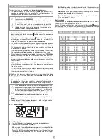
Releasing the gate should only be carried out when the motor has stopped so that the gate can be manoeuvred manually during blackouts.
To release the gate use the key supplied with the appliance. It should be stored in a safe and easily reachable place.
Release any electric brakes or locking devices before activating the manual release mechanism.
To release:
1) disconnect the electrical supply; 2) open the rubber cap, insert the key and turn it clockwise; 3) raise cover; 4) turn the lever towards the front of the ram; the gate
leaf can now be moved manually. 5) The gate leaf can remain unlocked and the cover can be refitted by simply removing the lever.
To lock:
6) grasp the lever and rotate towards the rear of the ram; at this point the leaf is locked and can only be moved electrically. 7) After this operation always close
the cover; 8) and turn the key to lock it in place; 9) take care to reclose the rubber cap protecting the lock.
ELECTRICAL CONNECTION


