background image

1

ZVL531.00 Mod: 27-08-2013

ENGLISH

ATTENTION!

 Before installing this device read the 

following instructions carefully!

Wiring diagram (installation example) 

Page 

2

Important remarks 

Page 

10 

Electrical connection 

Pages 

10-11

Programming procedure 

Page 

12-13

Display mode


Page 

 13

Remote control 

Page 

14

Function modes 

Pages 

14-15

Battery powered operation 

Page 

15

Indications on the display 

Page 

16

Technical specifications 

Page 

40

24 Vdc


Motors 

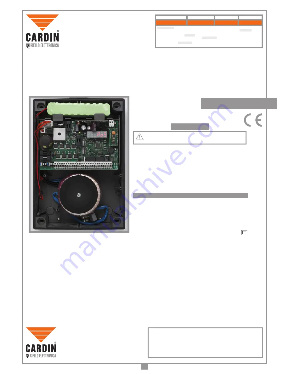
PROGRAMMATORE ELETTRONICO PER IL COMANDO DI PORTE E PORTONI MOTORIZZATI 

ELECTRONIC PROGRAMMER CONTROLLING MOTORISED GATES AND DOORS

PROGRAMMATEUR ÉLECTRONIQUE  POUR LA COMMANDE DE PORTES ET PORTAILS MOTORISÉS

ELEKTRONISCHER STEUERUNGSEINHEIT FÜR DIE AUTOMATISIERUNG VON TÜREN UND TOREN

PROGRAMADOR ELECTRONICO PARA EL CONTROL DE LAS PUERTAS MOTORIZADAS

Questo prodotto

 è stato testato e collaudato nei laboratori della casa costruttrice, la quale ne ha verificato la 

perfetta corrispondenza delle caratteristiche con quelle richieste dalla normativa vigente. 

This product

 has been 

tried and tested in the manufacturer's laboratory who have verified that the product conforms in every aspect to 

the safety standards in force. 

Ce produit

 a été testé et essayé dans les laboratoires du fabriquant. Pour l'installer 

suivre attentivement les instructions fournies. 

Dieses Produkt

 wurde in den Werkstätten der Herstellerfirma 

auf die perfekte Übereinstimmung ihrer Eigenschaften mit den von den geltenden Normen vorgeschriebenen 

getestet und geprüft. 

Este producto

 ha sido probado y ensayado en los laboratorios del fabricante, que ha 

comprobado la perfecta correspondencia de sus características con las contempladas por la normativa vigente.

Model

Date

Instruction manual

Series

PRG900

V01

01-02-2013

ZVL531.00

CARDIN ELETTRONICA spa 

Via del lavoro, 73 – Z.I. Cimavilla 

3 1 0 1 3   C o d o g n è   ( T V )   I t a l y

Tel:  

+39/0438.404011

Fax:  

+39/0438.401831

email (Italian): 

[email protected]

email (Europe): 

[email protected]

Http:

www.cardin.it

Vac 

230

Hz

50-60

1,2

 250

°C 

-20…+55

60 + 60

Electronic programmer specifications:

Power supply 
Frequency
Current input 
Maximum power yield 
Temperature range 
Power output for 1 or 2 motors 
Class II device 

Cls 

Inputs:

•  Radio frequency module aerial connection "

FM

•  NO inputs: opening button, limited opening button, closing button, dynamic button
•  NC inputs: inverting photocells, stop photocells, blocking button 

Outputs:

•  Outputs for: 1 or 2 motors; power: 

50 + 50 W

•  Output for a courtesy light with a potential free contact  

C-NO

•  Output for an indicator light 

24 Vdc 3W

•  Output for warning lights  

24 Vdc 25W

 (continuous or intermittent activation)

•  Output for an electric lock 

12 Vdc 15W


•  Output for external devices 

30 Vdc 7W

MHz 

433.92

MHz 

868.3

Nr. 

4

Nr. 

2

Incorporated receiver card:

Reception frequency S449 
Reception frequency S486 
Number of channels 
Number of functions 
Number of stored codes 

Nr. 

300

    TECHNICAL SPECIFICATIONS

C A R D I N   E L E T T R O N I C A   s p a 

Via del lavoro, 73 – Z.I. Cimavilla 

3 1 0 1 3   C o d o g n è   ( T V )   I t a l y

+39/0438.404011

Tel:  

Fax:  

email (Italian): 

email (Europe): 

Http:

+39/0438.401831

[email protected]

[email protected]

www.cardin.it

Содержание 24S-24L

Страница 1: ...enWerkst ttenderHerstellerfirmaaufdieperfekte bereinstimmung bereinstimmung seiner Eigenschaften mit den von den geltenden Normen vorgeschriebenen Merkmalengetestetund berpr ft Esteproductohasidoproba...

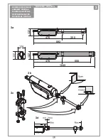
Страница 2: ...1 LEGEND 1 Geared motor SX left 2 Geared motor DX right 3 Internal photocells 4 External photocells 5 Warning lights 6 Mechanical selector switch 7 Electric locking device 8 External antenna RG58 coa...

Страница 3: ...FAHREN ESQUEMA DE MONTAJE 200 BLA24S 200 BLA24L SCALA 1 2 Prodotti TELCOMA BLA24 DI0290 Description Product Code Drawing number All rights reserved Unauthorised copying or use of the information conta...

Страница 4: ...reserved Unauthorised copying or use of the information contained in this document is punishable by law 476 350 137 893 476 500 1043 137 3 SCHEMA DI MONTAGGIO ASSEMBLY DRAWING SCH MA DE MONTAGE MONTAG...

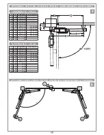
Страница 5: ...Unauthorised copying or use of the information contained in this document is punishable by law 105 55 94 27 8 5 10 5 4 SCHEMA DI MONTAGGIO ASSEMBLY DRAWING SCH MA DE MONTAGE MONTAGEVERFAHREN ESQUEMA...

Страница 6: ...240 200 270 240 1 200 BLA24L E 970 mm C A B alfa max 90 B alfa max 120 80 150 130 B 170 90 160 130 B 180 100 170 130 B 170 170 B 210 110 180 130 B 180 180 B 200 120 190 170 B 210 210 B 250 130 200 18...

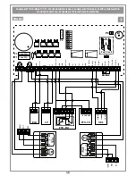
Страница 7: ...ned in this document is punishable by law SEL 24V 12V 0 C 1 6 5 4 3 2 NA NC NC C NA FTC RX 1 3 2 CLOSING COMMON OPENING 1 3 2 24V 12V 0 FTC TX 1 2 1 2 ELS LP BRIDGE CMN CMN FTCI N C TD N O CMN TA N O...

Страница 8: ...e recycling of materials Illicitly disposing of this product by the owner is punishable by law and will be dealt with according to the laws and standards of the individual member nation During the ope...

Страница 9: ...or one or two motors Before connecting the appliance make sure that the voltage rated on the data plate conforms to that of the mains supply The appliance works off a 24V direct current power supply s...

Страница 10: ...ebenen getestet und gepr ft Este producto ha sido probado y ensayado en los laboratorios del fabricante que ha comprobadolaperfectacorrespondenciadesuscaracter sticasconlascontempladasporlanormativavi...

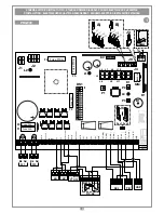
Страница 11: ...1 22 23 24 LC CH2 5 6 1 2 M1 CMN ELS 12V LS TAL N O FTCS N C P1 J1 B1 CS 1435 DC 0535 35 34 J4 R1 L9 L8 L6 L5 L10 L7 L4 P3 P2 L3 1 2 3 4 5 6 7 8 9 10 11 12 13 14 ON DS1 1 2 3 J5 Pos 1 Pos 2 1 2 3 CSP...

Страница 12: ...e product conforms in every aspect to the safety standards in force Any non authorised modifications are to be considered improper dangerous and the complete responsibility of the installer This appli...

Страница 13: ...Dip 10 OFF IfyouwanttoactivatetheFTCI FTCStestboththetransmissionandreceiverparts of the security devices must be connected to the binding post marked CTRL 24 Vdc If the test is active there will be...

Страница 14: ...motor 2 enabled OFF Travel limit motor 2 disabled Dip 14 Not used WHEN THE GATES REACH THE COMPLETELY OPEN POSITION THEY INVERT THE TRAVEL DIRECTION AND AFTER MOVING FOR A FEW CENTIMETRES THEY WILL OP...

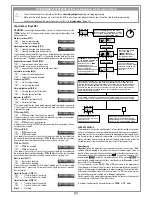
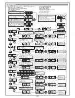
Страница 15: ...ng changes Deceleration settings 1 Minimum 3 Maximum 2 Medium PRESS PROG Each time the button is pressed the number increases from 1 to 3 10 sec 10 s after the last modification you will automatically...

Страница 16: ...he transmitter channel buttons memorised will activate their signal buzzer B1 fig 1 3 Press one of the channel buttons on the same transmitter The receivers which do not contain that channel code will...

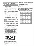
Страница 17: ...oor The self sufficiency of the system when it is running on battery power is dependent on the ambient conditions and on the load connected at binding posts 13 14 power is always routed there during b...

Страница 18: ...ng This happens when an N C contact is activated FTCI FTCS CSP during time programming or repositioning Once the passive state of the security devices has been reset the gate door will start moving ag...

Отзывы: