background image

19

fied engineer, who can also check the suitability of the power sup-
ply network. When the cooker is installed, check that the power
cable is not in contact with metal parts at the back of the cooker.
The power supply cable must be located so that it does not reach
at any point the temperature of 75°C. Do not use transformers
or shunters for connecting the appliance because these could
cause false contacts and dangerous overheating.

WARNING: It is the responsibility of the installer to ensure
that the standards referred to below are strictly adhered to.
The manufacturer declines all responsibility deriving from the
failure to apply these standards.
This appliance must be earthed. 

TIPS FOR INSTALLATION

Before proceeding with connection, check that:
the electrical supply can support the load of the appliance (see
characteristics booklet, Fig. 3, page 3);
the electrical installation is fitted with an effective earth in ac-
cordance with the regulations and provisions of the law;
the socket or the omnipolar cutout switch can be accessed easily
with the cooker fitted.

When the cooker has been installed, check that the power cable is
not in contact with the metal parts at the back of the cooker, and
that it does not at any point reach a temperature of 75°C.

CURRENT OPERATED EARTH LEAKAGE BREAKERS

Where the installation is protected by a 30 milliamp sensitivity
residual current device (RCD), the combined use of your cooker
and other domestic appliances may occasionally cause nuissance
tripping. In these instances the cooker circuit may need to be pro-
tected by fitting 100 mA device. This work should be carried out
by a qualified electrician.

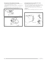
REPLACEMENT OF THE MAINS POWER CABLE

To replace the cable, it is necessary to select the type indicated
on the table below and follow the instructions (Fig. 33):
disconnect the appliance from the network
unscrew the screws located on the rear of the appliance and re-
move (Fig. 33)
unscrew the screw of the cable clamp
unscrew the screws in terminal C providing connection and remo-
ve the cable
thread the new cable into the cable clamp

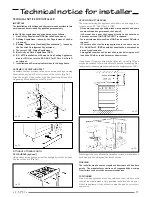
Connect the mains cable to the terminal following the diagram:
blue cable (neutral) connected to terminal N
brown live cable connected to terminal L
yellow/green cable connected to earth terminal (marked “C” in fig.
43).
tighten the screw of the cable clamp and refit the cooker taking
care not to crush the cables.

IMPORTANT:

When replacing the mains supply cable the installer must ensure
that the earth wire is longer than the live wires (Fig. 42) and re-
spect the prescriptions given below.

COMMENTS REGARDING OUR AFTER-SALES SERVICE

During the manufacture of your cooker, all requirements relating
to safety, as well as the international directives of the EEC, have
been respected. Furthermore, before leaving the factory, your
cooker was subject to a final check to ensure that all electrical
parts were operating correctly. We would be grateful if you would
also entrust the final work remaining on your cooker, namely its
connection to the mains, to a specialist, who must in this case be
a qualified installer. This is the only means of guaranteeing that
your cooker will operate appropriately and without danger.

fig. 41

fig. 42

fig. 43

Содержание CR1001SS

Страница 1: ...CR1001SS Range Cooker INSTRUCTIONS Recommendations for use installation maintenance of this appliance QualityProducts ConsumerHelpLine08702411142 Dir 89 336 CEE 73 23 CEE ...

Страница 2: ......

Страница 3: ... FOR YOUR SAFETY The installation must be performed by a competent installer properly qualified as required by local regulations Any rewiring required of the household electrics in order to install the cooker should only be carried out by a Qualified Electrician The manufacturer declines all responsibility for any type of damage resulting from failure to observe the regulations or from negligent i...

Страница 4: ... INSTRUCTION FOR USE P 6 TIMER FUNCTION P 11 COOKING GUIDE P 13 COOKER CLEANING P 13 COOKER SERVICING P 14 TECHNICAL NOTICE FOR INSTALLER P 17 BEFORE CALLING FOR ASSISTANCE P 21 ADDITIONAL NOTES FOR ASSEMBLING THE SAFETY CHAIN P 22 ...

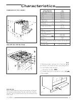
Страница 5: ...y read the technical data plate affixed to the inner side of the Plate War ming Door fig 3 This will indicate the series number and model of the cooker COOKER DIMENSIONS TWIN AND CHARACTERISTICS 100X60 Height of top a1 90 1 cm Depth C1 60 cm Width B 100 cm Height to top of splashback a2 96 1 cm Depth with over door open C2 94 cm Working capacity litres left 57 right 33 5 Class Combined and electri...

Страница 6: ...rent diameters and power ratings Use the appropriate burner for each type of pan as detailed below Twin model ovens and grills The standard conformation consists of a multifunction oven on the left and a static oven on the right The left oven is equipped with grill with an energy regulator The right oven is equipped with a fixed grill with turnspit Runners The shelves slot into the runners A These...

Страница 7: ...g symbols Fig 7 Oven off Oven light on it remains on in all functions 60 110 160 220 240 max oven temperature Bottom element on Top element on Grill element on turnspit on The red light indicates that one of the electrical components is on The yellow light indicates that the thermostat is on Using the electric grill The same knob that controls the electric oven Fig 7 also swit ches on the grill el...

Страница 8: ...llow light comes on This cooking mode is suitable for grilling meat fish and vegeta bles It can also be used for grilling bread and bacon Arrange the foods on the grill grid and place it on the chosen runners The oven door must be kept closed during grilling Turning the knob N 3 you can select a gradual variation of the grill cooking temperature main oven only Note When using the grill keep the ov...

Страница 9: ...e ra ting The red light confirms they are in operation Turn the thermostat knob 2 to the chosen temperature The yellow light comes on and will go out when the chosen tem perature is reached Arrange the foods on the grill grid and place it so that the foods are about 5 cm below the element Place the tray on the appropriate runners To prevent smoking pour a little water into the tray and keep the le...

Страница 10: ...in the oven This cooking mode is especially suitable for cooking large amounts of food such as roasts turkey etc Setting 8 rapid grilling fig 17 17 A Turn knob 1 to symbol Turn knob 3 to 6 The top electric element the grill the circular element at the back of the oven and the fan are operating The red light confirms they are in operation Turn the thermostat knob 2 to the chosen temperature The yel...

Страница 11: ... to turn on and off at a future time first press the COOKING DURATION button and adjust how long you wish the oven to cook with the buttons Then set the time you wish cooking to END by pressing the END TIME button and adjusting the time with the buttons Turn the Temperature and Function knobs to the desired positions The symbol A will appear on the screen When the oven turns an a cooking pot symbo...

Страница 12: ...partment The plate warming compartments are useful storage areas They get warm during use of the ovens and can be used to warm your plates or dishes Panset use Using a pan set in a right hand oven For cooking operations requiring the use of the oven shelf the tray provided should be placed in the runners beneath the shelf as shown in fig 20 in order to collect the drops of fat To grill using the P...

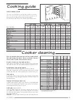
Страница 13: ...Door stripes Door seal Drip tray Baking tray Runners Grill set Grill grid Side Panels Knobs Handle Oven cavities Other Aerosols recommended for use on vitreous enamel For self cleaning ovens refer to page 13 Note Guide Only Cooking guide Cooker cleaning Never use detergent abrasive powder and strong cleaning products that might damage the surfaces Never use metal pads steel wool scourers knivesors...

Страница 14: ...ain parts Go to your SUPPLIER or contact our After Sales Department Give them the details provided on the DATA PLATE you will find thisontheinsideofthePlateWarmingDoor seeFig 3onpage3 They will have the parts list and technical documentation rela ting to our products and will quickly be able to supply you with any replacement parts and arrange for any necessary repairs to be carried out Replacemen...

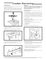
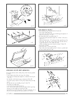
Страница 15: ...e and wipe off any excess grease check that the hole through which the gas passes is not blocked REPLACEMENT OF THE TAPS When replacing a tap follow the instructions below Remove the knobs by pulling Remove the hob and the control panel following the sequence of instructions in Fig 22 23 24 Take the burners apart as shown in Fig 29 Remove the ignition switch B Fig 29 if fitted after remo ving clip...

Страница 16: ...ws E Fig 31 2 with the burner free turn and unscrew screws F REPLACEMENT OR FITTING OF POWER SUPPLY CABLE Follow the advice below see Fig 33 Remove the rear panel of the cooker by unscrewing screws B Connect the power supply cable selecting the type indicated in the table on page 16 17 ELECTRICAL CONNECTION Replace the rear panel using the same procedure in reverse COMMENTS The earth conductor mus...

Страница 17: ... have an air supply in ac cordance with B S 5440 Part 2 1989 All rooms require an openable window or equivalent and some rooms will require a permanent vent as well if the room has a door that opens directly to the outside or the room exceeds 10m3 NO AIR VENT is required for room volumes between 5 and 10m3 an air vent of 50cm2 is required if there are other fuel burning appliances in the same room...

Страница 18: ...R THE DIFFERENT TYPES OF GAS Hob Burners remove the pan stands the flame dividers and the burner heads from their mountings select from the pack of injectors checking the corresponding indication on the injector the appropriate one for each burner and for the desired type of gas see table of technical charac teristics page 3 using a 7 mm spanner unscrew the injectors fitted Fig 39 Replace them wit...

Страница 19: ...these instances the cooker circuit may need to be pro tected by fitting 100 mA device This work should be carried out by a qualified electrician REPLACEMENT OF THE MAINS POWER CABLE To replace the cable it is necessary to select the type indicated on the table below and follow the instructions Fig 33 disconnect the appliance from the network unscrew the screws located on the rear of the appliance ...

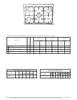
Страница 20: ...65 125 97 Z 166 3 Auxiliary burner A R H F 1000 330 50 73 50 71 72 X 95 4 Central burner BK central of LHF 3300 1350 91 240 91 235 125 Y 315 Nominal heat input full on W Nominal heat input reduced W ELECTRIC RIGHT OVEN STATIC CONVECTION KNOBPOSITION 0 Cooker types ABSORBED right POWER 0 900 600 1500 1500 oven THERMAL CAPACITIES DETERMINED WITH THE HIGH HEATING VALUE OF THE GAS AT 15 C 1013 mbar EL...

Страница 21: ...only as a guide Individual tastes may require the temperature to be altered either way to get the best results you want Try cooking at a higher shelf position and or higher temperature Is the oven door latching and sealing properly The oven is not cooking evenly Check that you are using the recommended temperatures and shelf positions Do not use a tin or tray larger than the baking tray we supplie...

Страница 22: ...The chain must be anchored to the wall behind the cooker in a cen tral position with respect to the width of the appliance in the fol lowing manner Firmly secure a hook A to the wall behind the cooker on the same level with the fixing points of chain C Fix chain C using the screws B situated at the back of the cooker fig 49 After having prepared the chain as above attach in to the hook A WARNING T...

Страница 23: ...that time should it become necessary CAPLE engineers will replace or repair all defective parts free of charge except for parts subject to fair wear and tear such as light bulbs Parts and the engineers labour costs are chargeable after the first 12 months To qualify for benefits under the guarantee you must be able to provide proof of date of purchase and the appliance must have been supplied inst...

Страница 24: ...2 12VFQ011640 GB spazio per targa dati ...

Отзывы: