CAPITOL HY- 6900 Скачать руководство пользователя страница 31


30

7.3 CLUTCH 


A) DISASSEMBLY 

NOTE: FOR REMOVAL  
INSTRUCTIONS SEE PAGE 22. 


1.  Remove socket head, capscrews, lock 

washers, (and Allen nuts) securing both 
clutch flanges to bevel gear carrier. 


2.  Lift off clutch flanges and clutch discs 


3.  Press and remove bearing and driving 

gear from both forward and reverse 
clutch flanges. 


4.  Remove locknuts, clutch identification 

tag and capscrews from outer perimeter 
of cylinders. 


5.   Separate and remove cylinder 


6.  Remove and discard quad rings from 

bevel gear carrier. 


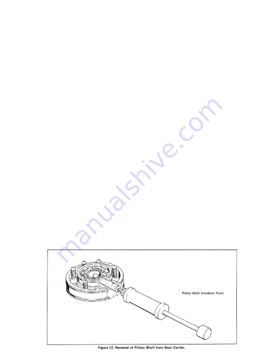
7.  Remove capscrews and locknuts 

securing pinion shafts in bevel gear 
carrier and remove bevel pinion shaft 
with puller (See special tool No. 1-
90008-0000, pinion shaft knockout 
puller). Refer to fig.22 


B) CLEANING AND INSPECTION


1.  Inspect bevel pinions for wear, 

chips, and breaks or out of round 
condition. If there is any damage 
we recommend replacing all of 
them as a set. 


2.  Check all pinion bearings and 

washers for distortion or rough 
operation. If one bearing needs 
replacement we recommend 
replacing all of them as a set. 


3.  Clean all parts with a good grade 

cleaning solvent or diesel fuel. Blow 
dry with compressed air. 


4.  Inspect all oil passages in bevel 

gear carrier to see that they are free 
from obstruction. 


5.   Inspect bevel gear carrier for 

cracks, chips or worn mounting 
surfaces. Pay special attention to 
seal ring grooves. Discard carrier if 
damaged. 


6.   Inspect forward commutator 

bushing for chips, heat scores, 
scratches, distortion or wear (See 
Wear limits, p. 23). Repair or 
replace as necessary. 


7.  Inspect all hardware and springs for 

wear or distortion. Repair or replace 
as necessary. 


8.  Remove clutch discs from flanges 

and inspect discs for broken teeth, 
heat scores or wear (See Wear 
Limits, page 23). Replace as 
necessary. 


9.  Inspect driving gear, and driven 

gear, for wear, chips or cracks. If 
either one is damaged we 
recommend replacing both as a set. 


Содержание HY- 6900

Страница 1: ...1 HY 6900 HY 7700 SERVICE MANUAL ...

Страница 2: ...AVAILABLE HORSEPOWER DO NOT OPERATE UNIT OVER 180º F 82ºC DO NOT OPERATE UNIT WITH HIGH OR LOW OIL PRESSURE DO NOT WINDMILL UNIT IN EVENT OF ENGINE FAILURE PROP SHAFT SHOULD BE LOCKED TO PREVENT WINDMILLING DO NOT ATTEMPT FINAL ALIGNMENT OF OUTPUT FLANGE AND PROP SHAFT COUPLING WHEN VESSEL IS IN DRY DOCK DO NOT SHIFT TRANSMISSION UNLESS ENGINE IS AT IDLE SPEED DO NOT USE TRANSMISSION TO SUPPORT RE...

Страница 3: ...dule and Check Sheet 13 Section 5 Trouble Shooting 5 1 Trouble Remedy Chart 14 Section 6 Repair of External Sub Assemblies 6 1 Oil pump 17 6 2 Selector Valve 20 Section 7 Repair of Internal Sub Assemblies 7 1 Removal of Reverse Gear 22 7 2 Table Replacement Wear Limits 23 7 3 Clutch 24 7 4 Pinion Shaft Removal and Reassembly 29 7 5 Output Gear and Related Parts 31 7 6 Housing Parts 32 7 7 Reassemb...

Страница 4: ...d Parts 52 8 11 Reduction Gear Selection Chart 54 8 12 Oil Filter 55 8 13 Propeller Coupling Kits 56 8 14 Oil Coolers 57 8 15 Hose and Fitting Kit 58 8 16 Housing and Related Parts Hy 6900 59 8 17 Pinion Shaft and Related parts Hy 6900 62 8 18 Output Gear and Related Parts Hy 6900 64 8 19 Reduction Gear selection Chart Hy 6900 66 Section 9 Reference Installation drawings Cross section Assembly dra...

Страница 5: ...5 ...

Страница 6: ...6 ...

Страница 7: ...on gear The adapter parts vary according to engine application and include a flywheel adapter drive flange and oil dam adapter to prevent engine contamination and driving drum The clutch pack consists of reciprocating cylinders clutch discs and a planetary bevel gear reversing system The oil and pump supplies oil pressure for clutch engagement and lubrication of bearings gears and clutch The selec...

Страница 8: ...The reduction ratio is the number of teeth in the reduction gear compared to the number of teeth in the pinion for example 144 teeth compared to 36 or 4 to 1 Output speed then is a product of engine r p m and the reduction ratio for example 200 r p m X 500 r p m output speed 2 3 POWER FLOW The flywheel adapter being directly fastened to the engine flywheel continually rotates the drive flange asse...

Страница 9: ...otate in engine direction reverse 2 4 CLUTCH The clutch assembly is a multiple disc type clutch activated by a hydraulic mechanism This mechanism is formed by a carrier for the bevel gears and by two cylinders bolted together which act as the clutch pistons The movement of the cylinders is regulated by the selector valve which directs pressurized oil to the proper cylinder depending on the mode se...

Страница 10: ... within the transmission housing In neutral the ports to both the forward and reverse sides of the clutch cylinder are opened and the balanced pressure that results keeps the clutch cylinder centered between the forward and reverse clutch discs Oil is distributed through the lubrication system When the selector valve is shifted to either forward or reverse mode high pressure oil is allowed to flow...

Страница 11: ...ing of 007 inch 2 Fig 3B Mount indicator with stern riding on flywheel housing bore as shown Rotate flywheel and record reading The bore eccentricity must not exceed a total indicator reading of 007 inch 3 Fig 3c Mount indicator to flywheel housing so that stern is on inner face of flywheel record deviation of face run out It must not exceed a total indicator reading of 007 inch 4 Fig 3D set stern...

Страница 12: ... reading Total indicator reading must not exceed 007 inch The sum of readings in steps 4 5 and 6 must not exceed 007 inch 12 Using and adequate hoist install clutch on splines of drive flange shaft being careful that clutch disc teeth enter driving drum properly Be sure that the forward end flange marked toward engine is placed toward the engine flywheel The forward pack contains the greater numbe...

Страница 13: ...operly without damaging teeth A screwdriver may be used through the side inspection hole to align disc teeth with the reverse drum 5 Secure transmission housing to oil dam adapter with capscrews and lockwashers 6 Check clutch end float insert screwdriver through side inspection hole and pry clutch fore and aft See fig 20 page 22 End float should be 1 16 to 3 32 7 Turn output coupling over for seve...

Страница 14: ...uplings Do not burr or mar mating surfaces Insert feeler gauge between couplings and run it all around the flange Clearance should not be more than 006 at any point Shim engine and reverse gear as necessary Mounting feet have threaded holes for jacking screws Loosen gear housing to engine housing bolts and check with feeler gauge Maximum variation for SAE 0 housing is 008 for SAE 1 housing is 006 ...

Страница 15: ...ing of the Capitol s reverse gear units connect the cooling system as indicated on one of the three diagrams shown It is extremely important that the marine gear oil be cooled properly the oil cooler must receive an ample supply of cold water ...

Страница 16: ...16 ...

Страница 17: ... for capacities Secure oil breather or inspection cover 7 Shift several times to insure that all cylinders hoses and cooler are full of oil 8 Install selector valve cables and shift to insure valve lever goes into full detent in all 3 positions forward neutral and reverse 9 Reverse gear is now ready for sea trials and final adjustments 3 7 OPERATING PRACTICES NOTE Normally unit pressure at idle st...

Страница 18: ...emove oil breather every 400 hours of operation or the same time oil is changed Clean diesel fuel can be used for flushing Pressure Gauge Periodically check pressure gauge by substituting a calibrated pressure gauge of known accuracy Visual Inspection At frequent intervals check all oil lines water hoses and connections for leaks Tighten all external bolts and connections and visually inspect exte...

Страница 19: ...e oil and flush sump Every 400 hours Check zinc pencils Change oil if contaminated Remove and clean oil breather and suction tube Replace filter element Every 2000 hours Check gear backlash seep 34 Check water tubes in cooler At engine overhaul Inspect clutch and all gearing and replace as necessary Inspect and or overhaul entire transmission Frequently Check all oil lines and connections Check al...

Страница 20: ...Remove drain plugs flush gear with commercial solvent or diesel fuel Start engine at idle shift gear several times full forward to full reverse for 3 5 minutes maximum Shut down engine and drain 7 Refer to oil pump section Page 17 or fig 13 p 11 8 See fig 13 page 11 9 Check heat exchanger system for clogged oil cooler or hoses 10 See wear limits chart p 23 11 See lube chart p 12 12 Replace as nece...

Страница 21: ...mbly 1 Remove oil pump and hoses Clean thoroughly and reinstall 2 Clean and replace as required 3 Oil level may be too low 4 Refer to oil pump section p 17 G Clutch does not release 1 Transmission is misaligned 2 Improper oil sump 3 Clutch discs warped 4 Forward and reverse clutch cylinders dirty or distorted 5 Rear commutator bushing is worn 6 Incorrect linkage adjustment to selector valve assemb...

Страница 22: ...d rings 5 Worn or damaged commutator bushings forward or rear 6 Worn selector valve 1 Refer to installation section 2 Replace as necessary 3 Replace as necessary 4 Replace all 4 5 Replace as necessary See replacement wear limits chart 6 Replace if necessary Note selector valve is the least likely source of trouble k Clutch engages too low 1 Cylinder timing screw out of adjustment 1 Remove dome nut...

Страница 23: ...at scores or distortions Burrs may be removed with fine crocus cloth otherwise plunger should be replaced 3 Clean all parts with a good grade cleaning solvent or diesel fuel Blow dry with compressed air 4 Generously lubricate relief plunger with oil or Vaseline Insert plunger cup end last Check plunger for free movement 5 Insert pressure relief spring into cup of plunger CAUTION Avoid contact with...

Страница 24: ... bushings in cover for wear see wear limits p 23 out of round condition or burrs If they are worn damaged or loose replace and ream to size see p 23 5 Inspect bushings 2 in adapter for wear out of round condition burrs If bushings are damaged replace as necessary and ream to size see p 23 6 Check relief plunger for free movement in adapter bore Replace if necessary 7 Inspect all mating surfaces fo...

Страница 25: ...and install new filter element in filter 2 Apply joint compound to threads and install pipe nipples bushing and oil filter to oil pump CAUTION FLOW ARROW ON FILTER MUST POINT AWAY FROM PUMP SEE FIG 16 3 Apply grease to bearing container and locate new oil pump gasket on container 4 Install oil pump and filter on bearing container Secure pump with capscrews and lockwashers and torque to 32 lb ft 5 ...

Страница 26: ...tor Match mark if desired Remove lever from rotor being careful not to lose indexing ball and spring 2 Remove key from rotor shaft 3 Note position of cover Remove cover cover gasket and rotor from block 4 Remove safety relief adjustment screw washers spring and plunger NOTE SPRING IS UNDER TENSION C CLEANING AND INSPECTION 1 Clean all parts thoroughly with oil and clean all oil ports Blow dry with...

Страница 27: ...position with a soft hammer and secure with retaining ring 5 Position new cover gasket on pilot face of cover 6 Install rotor with cover into selector valve body Secure cover with four capscrews Tighten to 4 pounds foot torque 7 Install safety relief adjustment parts in rear of valve body 8 Check for correct assembly by moving lever back and forth Selector valve is now ready to be installed on mai...

Страница 28: ...ansmission 7 Remove capscrews and lockwashers holding housing to oil dam 8 Insert screwdriver or similar object through side inspection hole to hold clutch assembly inside housing Slowly move housing aft and away from oil dam See fig 20 9 Remove clutch from forward driving drum Note See page 38 for adapter group repair CAPITOL GASKET AND SEAL KIT NO 1 10169 0000 HY 7700 1 10168 0000 HY 6900 Includ...

Страница 29: ... Teeth 150 160 140 Driven Internal Teeth 085 095 075 Driven Thick Internal Teeth 160 175 150 CLUTCH PACK THICKNESS Clutch 1 00100 6000 Forward Pack Compressed 1 645 1 785 1 505 Reverse Pack Compressed 1 410 1 530 1 290 CLUTCH PACK THICKNESS Clutch 1 00100 6300 Forward Pack Compressed 1 485 1 620 1 365 Reverse Pack Compressed 1 250 1 355 1 150 OIL PUMP IF DEEP GROOVES ARE PRESENT OR MORE THAN 006 C...

Страница 30: ...29 ...

Страница 31: ...we recommend replacing all of them as a set 2 Check all pinion bearings and washers for distortion or rough operation If one bearing needs replacement we recommend replacing all of them as a set 3 Clean all parts with a good grade cleaning solvent or diesel fuel Blow dry with compressed air 4 Inspect all oil passages in bevel gear carrier to see that they are free from obstruction 5 Inspect bevel ...

Страница 32: ...l it seats in bore The roll pins will lock the bushing in place and insure line up of oil holes in the bushing and bevel gear carrier 2 Installation of pinion shaft a To prevent damage to gear carrier and bearings the carrier should again be heated to expand the bore diameter b Apply lubricant on shafts and bores to ease fit C Gloves may be required since gear carrier is hot Insert protective 20 c...

Страница 33: ...essary readjust return spring height and install locknuts 5 Apply lube in seal ring grooves in bevel gear carrier and slip on four new quad rings avoiding twists in the rings 6 To Install cylinders A Apply a light coat of lubricant on inner walls of each clutch cylinder as well as quad rings B With forward side of gear carrier up press cylinder on by hand See fig 25 C Turn bevel gear carrier over ...

Страница 34: ...against the forward and reverse clutch flanges Refer to the appropriate illustration in section 7 parts information 10 Position reverse clutch flange and reverse clutch discs on reverse side of gear carrier flange on commutator bushing is on reverse side Position forward clutch flange with forward clutch discs and fasten both flanges to gear carrier Tighten capscrews to 25 pounds foot torque 11 Ch...

Страница 35: ...er head Discard element 2 Remove oil pump mounting bolts Remove oil pump discard gasket and remove oil pump drive shaft 3 Remove bearing retainer from cover Pinion will accompany it by tapping on pinion shaft if necessary from engine side of housing 4 Release tang of lockwasher and remove locknut and lockwasher from shaft 5 Using a suitable press extract pinion shaft from bearing retainer a protec...

Страница 36: ...spacer 2 Apply lubricant to bearing surface at threaded end of pinion shaft Press new bearing cone onto shaft snug against shoulder of gear Locate bearing spacer on shaft 3 Locate bearing retainer on pinion shaft 4 Press remaining bearing cone onto shaft Locate lockwasher 5 Apply lubricant to threads and install bearing locknut on shaft Secure by bending tang of lockwasher into slot on nut A prote...

Страница 37: ...nd remove pinion roller bearing mounted in housing 11 Press out rear commutator bushing Disassemble commutator by first removing snap ring at rear of assembly B CLEANING INSPECTING AND REPAIR 1 Inspect disassembled commutator bushing for cracked piston rings damage or wear see wear limits chart 2 Inspect tapered roller bearings on both ends of output shaft for rough rotation corrosion scoring scra...

Страница 38: ...faces of output coupling and propeller coupling and file smooth if possible Otherwise replace parts 8 Inspect housing cover bores and mating surfaces front and back Repair nicks or burrs with file or crocus cloth Clean all of the above parts thoroughly with solvent 2 6 HOUSING PARTS Set transmission housing upright 1 Flush clean and inspect main housing Inspect front and rear mating surfaces and r...

Страница 39: ...tor and press it into housing bore d Check that commutator sleeve floats in shell 3 If necessary replace reverse drum and secure with capscrews and lock washers Turn transmission housing engine end down 4 Install pinion roller bearing in housing bore Secure with snap ring 5 Install new output bearing cup if necessary in housing bore Make sure cup seats firmly 6 Install oil pan and secure capscrews...

Страница 40: ...p lightly if necessary so that shaft bottoms in bore 11 Apply new cover gasket to housing A small amount of grease may be used to keep gasket in place 12 Using adequate hoist install the housing cover onto dowel pins in housing Tap cover evenly with soft hammer until it is 1 8 from housing Locate capscrews and lockwashers Tap cover down firm and tighten capscrews 13 Install oiled bearing cup in ou...

Страница 41: ...way in output coupling by locating key and coupling temporarily on shaft Clearance should be 010 to 015 Otherwise file key as necessary 2 Heat output coupling in hot oil or water at 180q Fahrenheit or 82q Celsius for at least hour before installation 4 Install hot output coupling on output shaft Make sure coupling seats firmly against bearing If it does not a soft hammer should be used while coupl...

Страница 42: ...r 5 Apply oil pump gasket onto pinion bearing retainer with a small amount of grease 6 Install oil pump Secure with capscrews and lockwashers E R Models Only Connect idler hose to pump and idler shaft 7 Install new oil filter element in canister and install canister on filter head If head was removed make sure FLOW ARROW POINTS AWAY FROM PUMP when re installing 8 Connect suction hose Use joint com...

Страница 43: ...ntly twist pinion back and forth The play or backlash must be between 004 and 008 3 Check for gear tooth contact If a NEW pinion and or idler gear are installed check for tooth contact with marking compound Models without idler gear apply compound to pinion Units with idler gear apply compound to idler gear 7 11 ADDITIONAL ASSEMBLY 1 Install inspection covers and gaskets 2 Install oil breather and...

Страница 44: ... parts as necessary 2 Remove oil dam adapter and inspect labyrinth oil seal on inside diameter Repair or replace as necessary wear or damage to seal indicates misalignment check further 3 While oil dam is removed inspect flywheel adapter and drive flange for distortion or rough mounting surfaces Repair or replace as necessary ...

Страница 45: ...the address mentioned above Do not send any equipment to the factory without authorization from the customer service department Capitol Gears will route parts with customer s best interest in mind if routing is not specified when ordering Capitol Gears Inc Will provide its distributors dealers and service centers with current changes and additions to service literature Contact your local Capitol r...

Страница 46: ...R 1 01142 3400 1 7 CAPSCREW SOCKET HEAD 20X LG 1 09432 0800 4 8 LEVER 1 01143 4200 1 9 RETAINING RING EXTERNAL 1 13125 0000 1 10 KEY 3 32x DIA 1 01164 3200 1 11 SPRING PIN DIA X LG 1 12097 0800 1 12 OIL SEAL 1 01152 3200 1 13 SPRING INDEXING 1 01132 1500 1 14 BALL INDEXING DIA 1 11200 0000 1 15 ADJUSTMENT SCREW RELIEF 1 12617 0000 1 16 WASHER 003 THICK 1 12619 0000 5 17 WASHER 1 16 THICK 1 10288 0...

Страница 47: ...46 46 ...

Страница 48: ...11 BUSHING 7 8 O D X LG X BORE 12 DUR 1 11380 0000 4 12 BODY OIL PUMP 1 07856 0800 1 13 PIPE PLUG HEX SOCKET 3 8 N P T 1 11279 0400 1 14 GEAR PUMP 1 09688 0900 2 15 DISC FLAT 1 13731 0000 1 16 COVER OIL PUMP 1 07723 1100 1 17 LOCKWASHER 5 16 1 09458 0800 7 18 CAPSCREW HEX HD 5 16 18 NC X 2 12 1 10946 0000 7 19 SPRING PIN X 1 12097 1200 4 20 PIPE PLUG HEX SOCKET 1 16 27 N P T 1 11279 0100 1 21 PLAT...

Страница 49: ...48 48 1 5 CLUTCH Clutch no 1 00100 6000 ...

Страница 50: ... SOCKET HD 28X 2 1 09433 0800 3 11 THRUST WASHER 1 00221 3600 3 12 BEARING BEVEL PINION 1 00218 2500 3 13 PINION BEVEL 1 00217 2600 3 14 NAMEPLATE 1 12398 1200 1 15 NUT SELF LOCKING 5 16 18 NC 1 11399 0000 36 16 CYLINDER 1 00234 5500 2 17 QUAD RING 1 00237 3600 2 18 QUAD RING 1 00238 5800 2 19 CARRIER BEVEL GEAR 1 00219 3700 1 20 BUSHING FORWARD COMMUTATOR 1 00247 3600 1 21 SPRING PIN 1 12096 1000...

Страница 51: ...50 50 ...

Страница 52: ...000 2 26 NAMEPLATE 1 11210 0000 1 27 INSPECTION COVER REDUCTION HOUSING 1 06966 1100 1 28 GASKET INSPECTION COVER 1 06968 0800 1 29 HOSE I D 1 08873 0900 1 30 ELBOW MALE 45º 1 11220 1100 1 31 OIL STICK 1 07916 0800 1 32 BRACKET OIL STICK 1 07915 0900 1 33 TUBE OIL STICK 1 07915 0900 1 34 SHORT NUT 45º FLARE 1 11243 0800 1 35 ELBOW 90º 1 11237 1600 1 36 GASKET BEARING RETAINER TO PUMP 1 06762 0800 ...

Страница 53: ... SEE HY INSTALLATION DRAWING 1 4 HEX NUT HEAVY SLOTTED 1 06973 0800 6 5 COTTER PIN 1 12769 5400 6 6 BUSHING DRIVE FLANGE 1 00326 2600 1 7 OIL DAM ADAPTER SEE HY INSTALLATION DRAWING 1 8 COVER AIR VENT 1 01118 2700 1 9 LOCKWASHER 5 16 DIA 1 09458 0800 9 10 CAPSCREW HEX HD 5 16 18 X 1 12145 0000 4 11 DRUM CLUTCH DRIVING 1 01116 3600 1 12 CAPSCREW HEX HD POLYLOK 1 13804 0000 12 ...

Страница 54: ...53 53 8 8 PINION SHAFT AND RELATED PARTS 8 9 IDLER GEAR AND RELATED PARTS ...

Страница 55: ...12959 2600 1 8 LOCKWASHER BEARING 1 13235 0000 1 9 LOCKNUT BEARING 1 06903 0800 1 10 SHAFT PUMP DRIVE 1 07892 0800 1 IDLER GEAR AND RELATED PARTS ITEM DESCRIPTION PART NUMBER QTY 1 SNAP RING 1 10112 0000 2 2 BEARING ILDER 4 PIECES 1 10117 0000 2 3 IDLER 30 TEETH 1 10107 0000 1 4 SNAP RING 1 12763 0000 2 5 SHAFT IDLER 1 10105 0200 1 6 O RING 1 10336 0000 1 7 WROUGHT WASHER 1 10338 0000 1 8 LOCKWASH...

Страница 56: ...55 55 ...

Страница 57: ... 1 COVER RED GEAR HSG 3 1 RATIO WITH IDLER 1 10303 0000 1 COVER RED GEAR HSG 31 2 1 RATIO W IDLER 1 10313 0000 1 COVER RED GEAR HSG 4 1 RATIO W IDLER 1 10323 0000 1 COVER RED GEAR HSG 41 2 1 RATIO W IDLER 1 10333 0000 1 14 LOCKWASHER LIGHT 1 11083 0000 16 15 CAPSCREW HEX HD 1 09141 0800 15 16 DOWEL COVER TO HSG 1 12311 0000 2 17 CAPSCREW SOCKET HD 1 07544 0800 1 18 CONE BEARING 1 07707 1000 1 19 C...

Страница 58: ...EAR FOR YOUR TRANSMISSION A LOCATE THE NAMEPLATE ON TOP OF HOUSING AND DETERMINE THE TWO REDUCTION REATIO OPTION CODE NUMBERS CIRCLED IN SAMPLE BELOW AND THE RATIO THE NUMBER OF TEETH MAY BE CHECKED ALSO B MATCH THIS INFORMATION WITH THE CHART BELOW TO DETERMINE THE CORRECT PART NUMBER S ...

Страница 59: ...LTER 1 13811 0000 1 1 HEAD 1 13811 0100 1 2 SEAL HOUSING 1 13811 0500 1 3 ASSEMBLY ELEMENT INCLUDES ELEMENT SEAL 1 13811 0300 1 4 SPRING ELEMENT 1 13811 0600 1 5 HOUSING 1 13811 0200 1 6 CAPSCREW HEX HEAD 1 12339 0000 4 7 LOCKWASHER 1 09458 0800 4 8 PLUG DRAIN 1 11251 0500 1 ...

Страница 60: ...ELLER COUPLING KITS ITEM DESCRIPTION PART NUMBER QTY REF PROPELLER COUPLING KIT 1 13577 1000 1 1 NUT SELF LOCKING 10 NC 1 13095 0000 12 2 COUPLING PROP SHAFT 1 13826 0000 1 3 CAPSCREW HEX HEAD 10 NCX3 1 08793 0800 12 ...

Страница 61: ...ATER COOLER 17 X 5 1 8 DIA 1 13769 0000 1 2 FRESH WATER COOLER 19 1 2 X 6 1 8 DIA 1 13795 0000 1 3 SEA WATER COOLER 12 X 4 3 8 DIA 1 07808 5000 1 4 ZINC PENCILS 1 12445 0400 2 NOTE Hose and fitting kit no 1 13888 0000 may be ordered with any of the above oil coolers ...

Страница 62: ...61 61 ...

Страница 63: ...62 62 8 16 HY 6900 ...

Страница 64: ...NUT LIGHT 5 16 18 1 09464 0800 1 25 DRIVE SCREW ROUND HD 2X3 16 1 13275 0000 2 26 NAMEPLATE 1 11210 0000 1 27 INSPECTION COVER REDUCTION HOUSING 1 06966 1100 1 28 GASKET INSPECTION COVER 1 06968 0800 1 29 HOSE I D 1 08873 0900 1 30 ELBOW MALE 45º 1 11220 1100 1 31 OIL STICK 1 00330 3600 1 32 33 TUBE OIL STICK 1 02101 0300 1 34 35 36 GASKET BEARING RETAINER TO PUMP 1 06762 0800 1 37 SUB ASSEMBLY OI...

Страница 65: ...64 64 8 17 PINION SHAFT AND RELATED PARTS HY 6900 ...

Страница 66: ... 8 LOCKWASHER BEARING 1 13235 0000 1 9 LOCKNUT BEARING 1 06903 0800 1 10 SHAFT PUMP DRIVE 1 07892 0800 1 IDLER GEAR AND RELATED PARTS ITEM DESCRIPTION PART NUMBER QTY 1 SNAP RING 1 13991 0000 2 2 BEARING IDLER 9 4 PIECES 1 10117 0000 2 3 IDLER 30 TEETH 1 10107 1000 1 4 SNAP RING 1 12763 0000 2 5 SHAFT IDLER 1 10105 0200 1 6 O RING 1 10336 0000 1 7 WROUGHT WASHER 1 10338 0000 1 8 LOCKWASHER LIGHT 5...

Страница 67: ...66 66 HY 6900 ...

Страница 68: ...TIOS NON IDLER 1 10103 2100 1 COVER RED GEAR HSG 1 277 RATIO W IDER 1 10163 0000 1 COVER RED GEAR HSG 1 484 1 RATIO W IDLER 1 10123 0000 1 COVER RED GEAR HSG 2 037 1 RATIO W IDLER 1 10103 0000 1 COVER RED GEAR HSG 2 521 1 RATIO W IDLER 1 10133 0000 1 14 LOCKWASHER LIGHT 1 11083 0000 22 15 CAPSCREW HEX HD 1 09141 0800 22 16 DOWEL COVER TO HSG 1 12311 0000 2 17 18 CONE BEARING 1 06726 1000 1 19 20 S...

Страница 69: ...PUT GEAR FOR YOUR TRANSMISSION A LOCATE THE NAMEPLATE ON TOP OF HOUSING AND DETERMINE THE TWO REDUCTION RATIO OPTION CODE NUMBERS CIRCLED IN SAMPLE BELOW AND THE RATIO THE NUMBER OF TEETH MAY BE CHECKED ALSO B MATCH THIS INFORMATION WITH THE CHART BELOW TO DETERMINE THE CORRECT PART NUMBER S ...

Страница 70: ...69 69 ...

Страница 71: ...70 70 ...

Отзывы: