Chapter 4
4-17
3) Place the joint for the ink tube unit side in the ink flow path at the back of the ink tank unit.
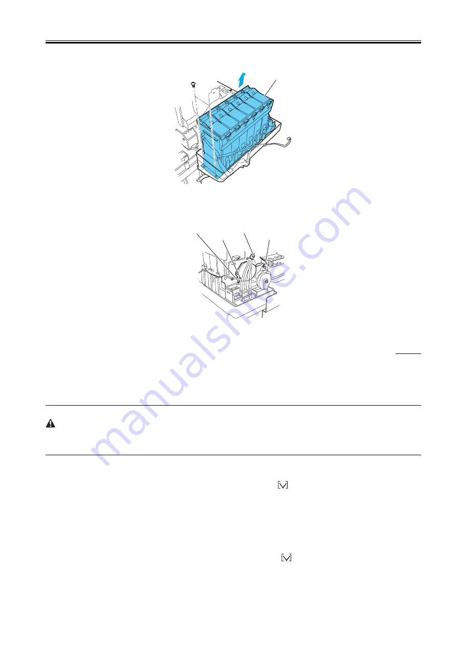
4) Remove the two screws and two connectors of the ink tank unit, and then remove the ink tank unit.
F-4-34
b) Removing the valve motor unit
1) Remove the two screws and detach the connector, then remove the valve motor cover.
2) Remove the two screws and the two connectors, then remove the valve motor unit.
F-4-35
4.3.12 Boards
0009-8792
Do not replace the system controller and engine controller at the same time.
Each controller has important stored information such as the setting values and carriage driving time. To retain this information, before a controller is
replaced, the information in the controller is temporarily stored in the other controller using internal communication. After the replacement, the information
is automatically written into the new controller. Therefore, the two controllers cannot be replaced at the same time.
Also, when the system controller and engine controller are replaced as service parts, check that the firmware version is the latest available. If it is not,
update the firmware to the latest version.
a) Replacing the system controller
When replacing the system controller original information of the following items in the MAIN MENU are not backed up and not restored in the new system
controller.
Save the original information accordingly, prior to the replacement of the system controller in case of need.
- MAIN MENU > Interface Setup > TCP/IP > IP Setting
1) Turn off the power and remove the power plug.
2) Replace the system controller.
3) Attach the power plug and then turn on the power while pressing the [Paper Source] button,
button, and [Stop/Eject] button. (The printer is started
in Board Replace mode.)
4) Check that "Initializing" appears on the display, and then release the buttons. (The message lamp turns on when the printer enters Board Replace mode.)
5) Wait until "REPLACE MODE" is displayed.
6) Select "S/C REPLACE", and then press the [OK] button.
7) Check that "Turn Power Off!!" is displayed, and then turn off the power.
8) Turn on the power.
9) Check the firmware version. If it is not the latest version, update the firmware to the latest version.
b) Replacing the engine controller
1) Turn off the power and remove the power plug.
2) Replace the engine controller.
3) Attach the power plug and then turn on the power while pressing the [Paper Source] button,
button, and [Stop/Eject] button.
(The printer is started in Board Replace mode.)
4) Check that "Initializing" is displayed, and then release the buttons. (The message lamp turns on when the printer enters Board Replace mode.)
Ink tank unit
Setscrew
Connector
Connector
Setscrew
Содержание W6400 Series
Страница 1: ...Apr 5 2005 Service Manual W6400 Series W6400 ...
Страница 2: ......
Страница 6: ......
Страница 12: ...Contents ...
Страница 13: ...Chapter 1 PRODUCT DESCRIPTION ...
Страница 14: ......
Страница 16: ......
Страница 40: ......
Страница 41: ...Chapter 2 TECHNICAL REFERENCE ...
Страница 42: ......
Страница 79: ...Chapter 3 INSTALLATION ...
Страница 80: ......
Страница 82: ......
Страница 86: ......
Страница 87: ...Chapter 4 DISASSEMBLY REASSEMBLY ...
Страница 88: ......
Страница 90: ......
Страница 115: ...Chapter 5 MAINTENANCE ...
Страница 116: ......
Страница 118: ......
Страница 122: ......
Страница 123: ...Chapter 6 TROUBLESHOOTING ...
Страница 124: ......
Страница 165: ...Chapter 6 6 39 F 6 7 Cover switch tool Cover switch tool ...
Страница 166: ......
Страница 167: ...Chapter 7 SERVICE MODE ...
Страница 168: ......
Страница 170: ......
Страница 185: ...Chapter 8 ERROR CODE ...
Страница 186: ......
Страница 188: ......
Страница 194: ......
Страница 195: ...Apr 5 2005 ...
Страница 196: ......


