Chapter 2 Product Overview
2-10
3) Open the Upgrade Kit package and check if every item is included. (See page 2-3.)
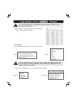
Confirm that the jumper receptacle is assigned to Slave, as shown in the figure below.
4)
Insert the Memory SIMM in Slot - 3 and Slot - 4. Connect the HDD cable to the HDD, and fix it to
the Main Frame with four Screws (d).
5) Perform the DIAG program, by connecting the power cord, setting the DIP switches for DIAG program,
and turning on the power, to check if the Upgrade Kit is installed correctly.
6) After the end of DIAG program, return the DIP switches to the OFF position.
7) Slide the Right Side Cover to close, and screw the Top Cover B. (See Step (2).)
8)
Perform Test Print, and confirm that the RAM amount is 128MB and that the HD2 amount is
2067MB(Free area is 1851MB). (For test printing, see page 3-12.)
Содержание PS-7000
Страница 11: ...Chapter 2 Product Overview 1 Product Composition 2 1 2 Main Unit 2 4 3 Specifications 2 7 4 Upgrade Kit 2 9 ...
Страница 23: ...Chapter 3 Troubleshooting 1 Troubleshooting 3 1 2 LED Indication 3 9 3 DIAG Program 3 10 4 Test Print 3 12 ...
Страница 37: ...Chapter 4 Disassembly Assembly 1 Disassembly 4 1 2 Assembly 4 12 3 About HDD Format 4 13 ...
Страница 38: ...Chapter 4 Disassembly Assembly 4 1 1 Disassembly 1 1 External appearance ...
Страница 51: ...Chapter 5 Operation Principles 1 RIP 5 1 2 Color Control 5 2 3 Miscellaneous 5 5 4 System Configuration 5 7 ...
Страница 63: ...Chapter 6 Parts Catalog 6 PARTS LAYOUT PARTS LIST 6 1 ...
Страница 64: ...Chapter 6 Parts Catalog 6 1 6 PARTS LAYOUT PARTS LIST 1 EXTERNAL COVERS 2 MAIN FRAME ...
Страница 65: ...Chapter 6 Parts Catalog 6 2 3 LED PANEL BOARD 4 INTERNAL COMPONENTS ...
Страница 66: ...Chapter 6 Parts Catalog 6 3 5 POWER SUPPLY UNIT 6 OTHER ...