3-40
CHAPTER 3. REPAIR INSTRUCTION
3.3.5 Starting up the Adjustment Software
After completing the preparatory steps, click Start and move the cursor to Program; then select Canon
Digital Camera and click PowerShot G5 Adjustment.
3.3.6 Menu Window
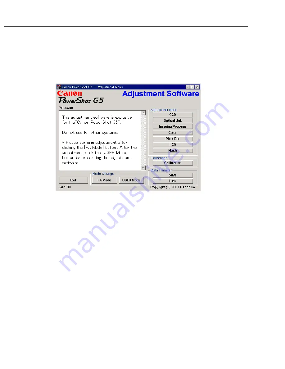
When the Adjustment Software starts up, the Menu Window below will appear.
3.3.7 How to Use the Adjustment Software
■
Mode change
This camera uses normally PTP for communication with PC. Because calibration and adjustment
become impossible depending on the condition of PTP, select the TWAIN mode of the PTP before
starting calibration and adjustment.
• “FA Mode” button: This button is used to change the mode from the USER mode to the FA mode.
(PTP to TWAIN)
* Before starting calibration and adjustment, be sure to set the FA mode.
• “USER Mode” button: This button is used to change the mode from the FA mode to the USER
mode. (TWAIN to PTP)
* When calibration and adjustment are completed, be sure to change the mode to the USER mode
before quitting the software.
■
Calibration/Adjustment
For starting, click the button related with calibration/adjustment.
* Whenever you use your light source for the adjustment for the first time, be sure to click the “Cali-
bration” Button.
■
Quitting the Adjustment Software
Click the “Exit” button.
■
Saving or Loading data
• “Save” button : This button saves all adjustment data stored on the camera in text format.
• “Load” button : This button loads all adjustment data saved in text format to the camera.
■
Notes
• If the adjustment fails, a message indicating the failure will appear on each product. If this happens,
do the adjustment again.
• The Adjustment Software is dedicated only to Canon Digital Camera PowerShot G5.
Never use it for any other camera.
• The Windows2000 or 98 must be pre-installed on the computer that is equipped with the USB
terminal.
* Operations on the other Operating Systems such as Windows95, Windows XP and others are not
guaranteed. (Because Windows95 does not support USB.)
Содержание PowrShot G5
Страница 1: ......
Страница 10: ...1 6 ...
Страница 11: ...1 7 ...
Страница 12: ...1 8 ...
Страница 19: ...3 3 Nomenclature Indicator LCD monitor 1 15 ...
Страница 21: ...1 17 Intervalometer Save Settings ...
Страница 30: ...1 26 4 2 Function s Availability and Data memory in Each Shooting Mode ...
Страница 31: ...1 27 ...
Страница 32: ...1 28 ...
Страница 34: ...1 30 ...
Страница 35: ...1 31 ...
Страница 36: ...1 32 ...
Страница 112: ...PowerShot G5 Pg2 INTERNAL PARTS SECTION 1 8 8 7 1 2 3 4 9 7 10 8 11 5 6 N S See Pg3 See Pg5 ...
Страница 116: ...PowerShot G5 Pg4 TOP COVER SECTION 23 24 22 1 3 7 15 4 5 6 8 24 20 16 18 19 14 21 17 9 10 11 12 13 2 ...
Страница 118: ...PowerShot G5 Pg5 EVF UNIT SECTION 1 10 2 5 3 7 12 11 12 4 6 8 13 9 a b a d c b d c ...
Страница 120: ...PowerShot G5 Pg6 BATTERY BOX UNIT SECTION 8 4 8 2 3 7 1 5 8 8 8 6 ...
Страница 122: ...PowerShot G5 Pg7 Fuse 2 1 DC DC CONVERTER PCB ASS Y ...
Страница 128: ...PowerShot G5 Accessories 3 Pg10 Camera User Guide Software Starter Guide System Map 1 2 Quick Start Guide 4 3 ...
Страница 147: ...C CANON INC 2003 01 JUNE 2003 3 3 STJ PCB ASS Y STJ PCB ASS Y SOLDERING SIDE STJ PCB ASS Y COMPONENT SIDE NF3 129 ...
Страница 148: ...C CANON INC 2003 01 JUNE 2003 3 4 HV MODULE UNIT ...
Страница 149: ...C CANON INC 2003 01 JUNE 2003 3 5 TOP MODULE UNIT ...
Страница 150: ...C CANON INC 2003 01 JUNE 2003 3 6 LCD PCB ASS Y ...
Страница 151: ...C CANON INC 2003 01 JUNE 2003 3 7 OPTICAL FLX ...
Страница 152: ...C CANON INC 2003 01 JUNE 2003 3 8 EF FLX ...
Страница 153: ...C CANON INC 2003 01 JUNE 2003 3 9 R_EN FLX ...
Страница 154: ...C CANON INC 2003 01 JUNE 2003 3 10 CCD FLX ...
Страница 156: ...PowerShot G5 Auto Focus Chart 1 ...
Страница 157: ...PowerShot G5 Auto Focus Chart 1 ...
Страница 158: ...AF Chart Dimensions 1 Dimensions 1 88mm 65mm ...
Страница 159: ...PowerShot G5 Auto Focus Chart 2 ...
Страница 160: ...PowerShot G5 Auto Focus Chart 2 ...
Страница 161: ...AF Chart Dimensions 2 228 5mm 170mm ...


