background image

3-48

CHAPTER 3.  REPAIR INSTRUCTION

3.3.4

Starting up the Adjustment Software

After completing the preparatory steps, click Start and move the cursor to Program; then select Canon
Digital Camera and click PowerShot G2 Adjustment.

3.3.5

Menu Window

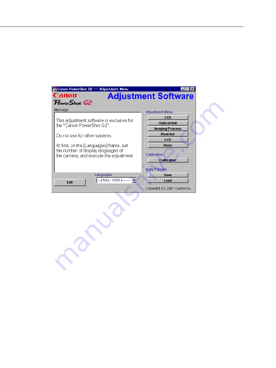
When the Adjustment Software starts up, the Menu Window below will appear.

3.3.6

How to Use the Adjustment Software

Calibration/Adjustment

For starting, click the button related with adjustment.

* Whenever you use your light source for the adjustment for the first time, be sure to click the “Cali-

bration” Button.

Quitting the Adjustment Software

Click the “Exit” button.

Saving or Loading data
•  “Save” button : This button saves all adjustment data stored on the camera in text format.
•  “Load” button : This button loads all adjustment data saved in text format to the camera.
Saving or Loading data
•  “Save” button : This button saves all adjustment data stored on the camera in text format.
•  “Load” button : This button loads all adjustment data saved in text format to the camera.
Notes
•  If the adjustment fails, a message indicating the failure will appear on each product. If this happens,

do the adjustment again.

•  The Adjustment Software is dedicated only to Canon Digital Camera PowerShot G2.

Never use it for any other camera.

•  The Windows98 must be pre-installed on the computer that is equipped with the USB terminal.

(Windows95 does not support the USB.)
* The operation with the Win2000, WinMe, etc. is not guaranteed.

Содержание PowerShot G2

Страница 1: ...4 System Accessories 1 12 2 5 Application Software 1 13 3 Exterior 3 1 Exterior Photos 1 16 3 2 6 dimensional diagram 1 17 3 3 Nomenclature 1 18 3 4 UI display 1 19 4 Specifications 4 1 Camera Specifications 1 23 4 2 System Requirement 1 29 4 3 Accessory Specification 1 30 5 System 5 1 Accessories compatibility 1 31 5 2 System Diagram 1 33 CHAPTER 1 GENERAL DESCRIPTION OF PRODUCT CONTENTS ...

Страница 2: ...m of preserving the basic concepts and assets of the PowerShot G1 while also providing the best image quality and the latest functions for advanced amateurs and commercial users including a 4M pixel CCD the most pixels in the compact camera class a new imaging engine primary color filters three light metering modes direct print support color effect modes and continuous rapid shooting capability 1 ...

Страница 3: ...r Q2VGA N AF modes that permit switching the ranging points three points available with continuous AF and singleAF N Digital zoom function with continuously changing viewing angle approximately 11x when used in combination with optical zoom N AE lock FE lock The combination of shutter speed and numeric aperture can be changed after AE is locked N Evaluation metering center weighted averaging meter...

Страница 4: ...d into body of camera and a strap attached to the camera at both ends allow user to hold camera securely Wide converter lens teleconverter lens and close up lens N Compatible with EX series Speedlites for EOS cameras Also permits use of Macro Ring Light ZoomBrowser EX 2 8 Win ImageBrowser 1 8 Mac featuring improved ease of operation Photorecord 1 2 Win for easy layout and printing of many pictures...

Страница 5: ...eration Unlike the front of the camera the curved surface that forms the rear of the camera is expressive producing a molded contrast l Improved holding The camera body incorporates a grip of the ideal size and shape while not making the camera any less portable l Improved portability The newly developed wide strap with an anti slip surface is now attached to the camera at both ends The portabilit...

Страница 6: ... averaging Spot Center weightedaveraging Spot Exposurecontrol method Program AE Shutter speed priority AE Aperture priority AE Manual Exposurecompensation 2 0EV at every 1 3 stop ISO speed equivalent ISO50 400equivalent W 0 7 4 5m T 0 7 3 6m Whitebalance Auto Preset 6position Manual Auto Preset 5position Manual Shootingmode Auto Creative Program additional of Color effects not equip Color effects ...

Страница 7: ...IGITAL 300 200 and the PowerShot A20 A10 primary color type filters have been adopted for the PowerShot G2 as the CCD on chip filters for colorization With the primary color type filters filters for the three colors R G and B are positioned on the CCD in a regular pattern Although this type of filter offers excellent color reproduction the principles behind it result in inferior performance in ter...

Страница 8: ... as when shooting pictures with illumination from an unusual light source or from a mixture of different light sources This data is saved even when the camera is turned off and can be updated by repeating the manual white balance setting operation l Highly detailed and fast processing using a dedicated digital signal processing IC The PowerShot G2 utilizes the Digital signal processing IC that was...

Страница 9: ...XYDIGITAL300 200 is not implemented in the PowerShot G2 If the amount of free CF capacity is less that the buffer capacity recording continues for the length of time determined by the free CF capacity After the buffer becomes full data is written to the CF It is not possible to shoot the next image while data is being recorded in the CF l AF modes that permit switching the ranging points three poi...

Страница 10: ... the zoom operation becomes slower after the transition is made from the optical zoom region to the digital zoom region In the PowerShot G2 however the functions provided by the new imaging engine allow digital zoom and optical zoom to be performed at equivalent zoom speeds so that there is no difference that is noticeable in actual use l AE lock FE lock The combination of shutter speed and numeri...

Страница 11: ...s approximately 5 pictures which is fewer than is possible with the conventional continuous shooting mode 1 5 pictures per second which can be shot at the amount of approximately 9 pictures When the buffer becomes full regardless of which mode was selected the continuous shooting speed slows due to the need to create space for each picture while continuing to shoot Shooting can still continue at t...

Страница 12: ...ical on the zoom bar and move the position of the frame using directional button In order to implement the direct print function the camera s own internal processor must rapidly perform color processing for the printer that ordinarily would be handled by the printer driver of a computer meaning that the proces sor must be able to perform such operations quickly and color processing itself must be ...

Страница 13: ...ash photography in macro mode A separate Macro Ring Light adapter 58C is needed in order to mount the light on the camera The table 2 6 1 shows compatibility of flash functions and system Photo 2 3 BP 511 Photo 2 4 BP 512 Photo 2 5 Macro ring light MR 14EX 1 Flashes will emit fully when the PS G1 is set to manual mode When setting the PS G2 to manual mode and operating the flash from the UI s on t...

Страница 14: ...hen using RemoteCapture it is possible to perform the following operations from the PC Release operation single shots interval shots timer shots Setting the zoom position except for digital zoom Checking various shooting parameters that are set in the cam era Setting the number of recording pixels compression factor macro mode the white balance exposure compensation etc Setting whether or not to s...

Страница 15: ...ent print ZoomBrowser EX 2 8 Layout printing PhotoRecord 1 2 4 Panoramic image composite PhotoStitch 3 1 3 PhotoStitch 3 1 2 Shooting PC transportation RemoteCapture 2 0 RemoteCapture 2 0 Camera driver USB TWAIN Driver 3 8 USB WIA Driver 3 8 for Win Me Plug In Module 3 8 USB Mounter 1 0 Utility of RAW image development RAW Image Converter 1 1 RAW Image Converter 1 1 Playback of movie Apple QuickTi...

Страница 16: ...4567890123456789012345678901212345 123456789012345678901234567890121234567890123456789012345678901212345 123456789012345678901234567890121234567890123456789012345678901212345 123456789012345678901234567890121234567890123456789012345678901212345 123456789012345678901234567890121234567890123456789012345678901212345 123456789012345678901234567890121234567890123456789012345678901212345 123456789012345...

Страница 17: ... z Accessories Adition to PowerShot G1 Photo 3 1 PowerShot G2 front Photo 3 2 PowerShot G2 back Photo 3 3 PowerShot G2 top Photo 3 4 PowerShot G2 side Photo 3 5 BP 512 Photo 3 7 Macro ring light MR 14EX Photo 3 6 Adapter for Macro ring light 58C ...

Страница 18: ...1 17 3 2 6 dimensional diagram Unit mm inch 118 7 4 67 120 9 4 76 76 6 3 02 74 3 2 93 63 8 2 51 51 7 2 04 ...

Страница 19: ...ctor MENU Button SET AF frame select Button AE Lock FE Lock Erase Button DISPLAY Button Exposure Whitebalance AEB Flash Exposure Compensation Button Macro JUMP Button Remote Sensor Optical Viewfinder Window Strap Holder Built in Flash AF Auxiliary Light Emitter Red eye Reduction Lamp Self timer Lamp MF Manual Focus Button Speaker Terminal Cover A V OUT Video Audio Terminal Battery Cover Button Bat...

Страница 20: ...ing n Information during display n Setting display Number of recording pixels Compression level Shutter speed Aperture setting MF Indicator Remaining image capacity Remaining passing time of movie AF frame Spot metering shooting Prepares the camera for shooting SET Button MENU Button Prepares the camera for shooting SET Button MENU Button Button Button Button ...

Страница 21: ... level are also changed to the set new mode l In spite of power off set number of recording pixels and compression level have to keep its setting Prepares the camera for shooting Prepares the camera for shooting MENU Button MENU Button Flash White Balance AEB Exposure WB AEB Flash exposure Button l All of settings set up SET Button n Setting Exposure compensation White balance AEB Flash Exposure W...

Страница 22: ...ed with power off MENU Button Shooting data time ISO equivalent speed Shutter speed DISPLAY Button File number Image number Replay image number Total number of images Nine images can be shown in the display Index replay Jump between images Replay DISPLAY Button DISPLAY Button Aperture Histogram Selected image JUMP Button Index Button Jump cover JUMP Button Setting Exposure compensation White balan...

Страница 23: ... when the camera is set to the replay mode and connect to the CP 10 Card Photo Printer Direct printing SET Button SET Button MENU Button MENU Button Print style Number of prints Trimming SET Button Display of rotation Prepares the camera for shooting ...

Страница 24: ...35mm film equivalent 2 0 W 2 5 T Normal AF 70 cm 2 3 ft infinity Macro AF 6 0 2 ft W 20 0 7 ft T 70 cm 2 3 ft Manual Focus 6 0 2 ft W 20 0 7 ft T infinity Max shooting area Wide 82 X 60 mm Tele 84 X 62 mm When attached Close up lens 250D 58mm Tele 50 X 38 mm 7 groups 8 pieces Real image optical zoom viewfinder 0 31 W 0 93 T Vertical 84 Horizontal 84 When object is 3m away 3 0 1 0 dpt Low temperatu...

Страница 25: ... shoe Canon SPEEDLITE 220EX 380EX 420EX 550EX Macro Ring Light MR 14EX 2 0EV at every 1 3 stop FE Lock is available Auto Creative zone Program Shutterpriority AperturepriorityandManual Programmed Image Control zone Pan focus Portrait Landscape Night scene Color effects Stitch assist and Movie Hight speed Approx 2 5 images sec at Large Fine mode and LCD viewfinder is OFF Maximum of 5 images can be ...

Страница 26: ... 8 bits Color signal Cr Cb 8 bits Any documents to be distributed outside the company should state that Above written figures are measured under Canon s standard conditions and may vary depending on the scene subjects or cam era settings L SF L F L N M 1 SF M 1 F M 1 N M 2 SF M 2 F M2 N S SF S F S N File Size 2002KB 1116KB 556KB 1002KB 558KB 278KB 570KB 320KB 170KB 249KB 150KB 84KB FC 8M 3 6 13 7 ...

Страница 27: ...tery completed adequate charge for use Blinks in orange Indicates that the camera is ready camera shake warning During charging battery Blinking interval is vary depending on recharging conditions Lights in yellow SW1 ON in macro shooting Manual focus shooting Blinks in yellow Indicates that the focus goes to fixed point because the actual focus point is not found Rechargeable Lithium ion battery ...

Страница 28: ...M2 S Movie 320 240 Movie 160 120 Superfine Fine Normal JPEG RAW AVI ISOequivalent speed Auto only Auto only Auto only Auto only Auto only Auto only Auto only Auto only 2 Digital zoom Continuous Single Contrast Sharpness Color saturation Creative Image Auto Focusing method Recording format Compression level Recording pixels Shooting Flash default selectable selectable for the first picture only not...

Страница 29: ...to definite movie shooting timesize Corrupted data message displayed Since the PS G2 PS G1 Pro90 IS EOS D30 s RAW has an internal JPEG file for playback a full screen image is displayed However if the RAW from the PS A50 and previous models is played back with the PS G2 PS G1 Pro90 IS EOS D30 thumbnails will be deiplayed Playback Compatibility PS 350 PS A5 A5Z PS Pro70 PS A50 PS S10 S20 IXY DIGITA...

Страница 30: ...capture 2 0 20MB and over Raw Image Converter 1 1 10MB and over USB TWAIN Driver 3 8 25MB and over USB WIA Driver 3 8 25MB and over Adobe Photoshop LE 40MB and over ImageBrouser 1 8 20MB and over PhotoStitch 3 1 30MB and over Remotecapture 2 0 15MB and over Raw Image Converter 1 1 10MB and over USB Mounter 1 0 5MB and over USB Plug In Module 3 8 15MB and over Adobe Photoshop LE 40MB and over Displ...

Страница 31: ...FV100 Type Lithium ion secondary battery Nominal Voltage DC 7 4V Nominal Capacity Approx 1 100 mAh Operating Temperature 0 40C 32 104F Operating Humidity 65 or less RH Dimensions WXHXD Approx 38 X 55 X 21 mm Weight Approx 70g 2 5oz 38 1 5 21 0 83 55 2 2 Unit mm inch Fig 4 1 Battery Pack BP 512 ...

Страница 32: ...512 O NB4 100 O Adapter Charger CA PS100 100E O O O CA PS200 O CA PS300 O CA PS500 O O O 1 O CA 560 O O O CR 560 O O O CB 2L 2LE O CB 2LS 2LSE O O CB 3AH O CBK 100 O 1 It is available to connect adapter s DC plug to camera s DC IN jack directly DC coupler DR 100 100A O O O DR 200 O DR 300 O DR 500 O O Lens accessories WC DC58 O O O WC DC52 O TC DC58 O O 250D 58mm O O 500D 58mm O 250D 52mm O LA DC5...

Страница 33: ...0 O AVC DC100 O O O O AVC DC200 O IFC 100PCS O O O IFC 100MC O O O IFC 200PCS O O O IFC 200PCU O O O O O O IFC 200MC O O O O IFC 300PCU O O AD PC98 O O O O O O PS A20 only Case SC PS100 O O O SC PS300 O O SC PS400 O O SC PS500 O SC PS600 O SHC PS200 O SHC PS300 O All Wether Case Water Proof Case AW PS100 O AW PS110 O AW PS200 O O WP DC100 O WP DC200 O ...

Страница 34: ...TT BATT OPEN OPEN OPEN OPEN LOCK BATT OPEN Battery Pack BP 511 512 Hot shoe SPEED LIGHT EX 220EX 380EX 420EX 550EX MR 14EX Macro Light Adapter LA DC58 Remote Controller WL DC100 Tele Converter TC DC58 Wide Converter WC DC58 TV monitor AV Cable AV DC100 I F I F I F I F AV AV AV AV F F F I F AV AV AV AV Conversion LensAdapter LA DC58 G1 Battery Chamber Close up Lens250D 58mm EOScompatible CF Card Ty...

Страница 35: ...Circuits 2 1 Power Supply Control 2 2 2 1 1 Power Supply Block Diagram 2 2 2 1 2 Power Supply Control Sequence 2 2 2 2 Signal Processing 2 3 2 2 1 System Control 2 3 2 2 2 Picture Processing 2 4 2 2 3 Audio Processing Recording and Playback Functions 2 4 3 Troubleshooting 2 5 3 1 When an Error Code is Displayed 2 5 3 2 When a Problem Occurs 2 7 CHAPTER 2 TECHNICAL DESCRIPTION CONTENTS ...

Страница 36: ... Refer to Section 2 2 2 5 Video output Refer to Section 2 2 2 6 Microphone input and sound output Refer to Section 2 2 3 1 2 DC DC CONVERTER PCB ASS Y 1 Power supply drive DC DC converter 2 Battery charging control circuit 1 3 LCD PCB ASS Y 1 Image display 2 Backlight for LCD drive 1 4 TOP MODULE UNIT 1 Operation switch operation display and finder LED 1 5 BUTTON PCB ASS Y 1 Flash control 1 6 FLAS...

Страница 37: ... position when Battery is Installed CPU activates the other main functions E0 Operating the Dial Switch Rec Mode Play Mode 1 Controls CCD E2 2 Controls LCD E3 3 Controls LCD backlight E5 1 Controls LCD E3 2 Controls LCD backlight E5 Battery charging operation starts when external power is supplied to DC IN connector CPU DSP REG MAIN PCB ASS Y DC DC CONVERTER PCB ASS Y DC DC CONVERTER E0 OUTPUT E2 ...

Страница 38: ...d conversion of the digital data LCD Driver Driving the LCD FLASH MEMORY Firmware and adjustment data memory DSP Picture processing RTC Clock count for watch AF Support LED AF auxiliary self timer and red eye protection also serves as a lamp Electric Flash Flash and charging circuit CDS A D LCD Driver CCD Sensor LENS Motor Driver AF Support LED FINDER LED Electric FLASH CF card LCD TG Video Amp RT...

Страница 39: ...ing the SDRAM Writes and reads the picture data to and from the CF card Outputs the picture data to the CPU Outputs analog video signal to the LCD and VIDEO OUT 3 The video signal that is supplied form the DSP is controlled by the LCD driver and is displayed on the LCD The video amplifier is activated when the AV jack is inserted to the video jack and drives the video signal in 75 Ω 2 2 3 Audio Pr...

Страница 40: ...on error was detected Cause and Probable Faulty Part MAIN PCB ASS Y OPTICAL UNIT MAIN PCB ASS Y OPTICAL UNIT MAIN PCB ASS Y OPTICAL UNIT MAIN PCB ASS Y UNKNOWN MAIN PCB ASS Y MAIN PCB ASS Y OPTICAL UNIT OPTICAL UNIT MAIN PCB ASS Y The lens barrel is fed out with the lens cap attached Remedy Remove the lens cap and restart the camera OPTICAL UNIT MAIN PCB ASS Y Either zoom movement is obstructed by...

Страница 41: ...S Y was not detected Detection of the focus PI photo interrupter failed Writing of the photograph image to SDRAM did not end within the specified time Free area could not be secured in the buffer for the photograph image within the speci fied time in the continuous shooting mode The camera power was turned OFF while the image was being recorded to the CF Card Micro Drive while the green LED was bl...

Страница 42: ...Y BOX MAIN UNIT BATTERY EJECT SPRING POWER LEAD HINGE UNIT MAIN PCB ASS Y BUTTON PCB ASS Y LCD PANEL LCD PCB ASS Y BACK LIGHT UNIT HINGE UNIT LCD PCB ASS Y MAIN PCB ASS Y OPTICAL UNIT MAIN PCB ASS Y OPTICAL UNIT MAIN PCB ASS Y ZOOM BRUSH TOP MODULE UNIT B W LCD PANEL CONTACT RUBBER TOP MODULE UNIT MAIN PCB ASS Y FLASH UNIT DC DC CONVERTER PCB ASS Y TOP MODULE UNIT Problem when an error code is not...

Страница 43: ...Y TOP MODULE UNIT MAIN PCB ASS Y MODE DIAL BRUSH TOP MODULE UNIT MAIN PCB ASS Y BATTERY BOX MAIN UNIT DATE LEAD BUTTON PCB ASS Y MAIN PCB ASS Y DC DC CONVERTER PCB ASS Y Problem when an error code is not displayed The External Flash does not fire Video output is strange Communications with the personal computer is not possible The CF card or Micro Drive is not recognized Sound cannot be recorded S...

Страница 44: ...5 CF UNIT BATTERY BOX UNIT 3 20 2 2 16 DC DC CONVERTER PCB ASS Y 3 21 2 2 17 TRIPOD BASE 3 22 2 3 Disassembly of Main Units 3 23 2 3 1 TOP UNIT 3 23 2 3 1 1 TOP UNIT 3 23 2 3 1 2 ZOOM LEVER UNIT 3 24 2 3 1 3 MODE DIAL 3 25 2 3 1 4 ACC SHOE 3 26 2 3 1 5 ACC SHOE UNIT 3 27 2 3 1 6 B W LCD WINDOW UNIT 3 28 2 3 1 7 MAIN BRUSH 3 29 2 3 1 8 B W LCD PANEL 3 30 2 3 2 FLASH SPEAKER UNIT 3 31 2 3 2 1 FLASH ...

Страница 45: ...3 4 Starting up the Adjustment Software 3 48 3 3 5 Menu Window 3 48 3 3 6 How to Use the Adjustment Software 3 48 3 4 Calibration 3 49 3 4 1 Calibration 3 49 3 5 Adjustment Procedure 3 54 3 5 1 Language setting 3 54 3 5 2 CCD Adjustment 3 55 3 5 3 Optical Unit Adjustment 3 57 3 5 4 Imaging Process Adjustment 3 59 3 5 5 Pixel Dot Adjustment 3 64 3 5 6 LCD Adjustment 3 66 3 5 7 Flash Adjustment 3 67...

Страница 46: ... circuit 1 2 List of Tools The following tools are used for the re assembling during service 1 List of tools New Name of tools Part No Areas where supplies are used Screwdriver Local Purchase Tweezers Local Purchase Soldering iron Local Purchase Steel wire φ1 2mm Local Purchase FINDER UNIT 1 3 List of Supplies The following supplies are used for the re assembling during service 1 List of supplies ...

Страница 47: ...ng the tweezers into them as required 1 4 Flexible Connectors This product uses the four types of the flexible connectors Fig 3 3 Holes for removal Fig 3 2 Flexible connectors LOCK UNLOCK LOCK UNLOCK UNLOCK LOCK 4 Type D 3 Type C Unconnected state Connected state Unlocked state Locked state Unlocked state Locked state Unlocked state Locked state Holes 1 Type A 2 Type B The contact piece should fac...

Страница 48: ...pper unit 2 The paralleled units can be removed arbitrary without order START FRONT COVER UNIT 3 4 GRIP COVER 3 5 SIDE COVER JACK COVER 3 8 CF COVER 3 7 REAR COVER UNIT 3 6 TOP UNIT 3 9 3 23 MAIN PCB ASS Y 3 11 REAR PLATE UNIT 3 14 3 33 LCD HINGE UNIT 3 10 3 38 FLASH SPEAKER UNIT 3 12 3 31 JACK PCB ASS Y 3 13 MAIN SHEET 3 15 DC DC CONVERTER PCB ASS Y 3 21 FINDER UNIT 3 16 CF UNIT 3 20 BATTERY BOX ...

Страница 49: ...r touch the terminals of the capacitor Be sure to discharge the capacitor with the discharging resistor about 1kΩ 5W 1 3 FRONT COVER UNIT 1 6 FRONT RING 1 1 1 2 1 4 1 5 Capacitor Terminals Dowels 1 2 1 4 1 4 2 2 1 FRONT COVER UNIT 1 FRONT COVER UNIT 1 Remove the FRONT RING 2 Remove the two screws 3 Remove the STRAP RING UNIT 4 Remove the three screws 5 Remove the two dowels and FRONT COVER UNIT CA...

Страница 50: ...3 5 CHAPTER 3 REPAIR INSTRUCTION Fig 3 5 GRIP COVER t 1 1 GRIP COVER 1 2 b j 1 1 1 1 Dowels 2 2 2 GRIP COVER 1 GRIP COVER 1 Remove the four screws 2 Remove the two dowels and remove the GRIP COVER ...

Страница 51: ...2 2 3 REAR COVER UNIT 1 REAR COVER UNIT 1 Remove the two screws 2 Remove the STRAP RING UNIT 3 Open the CF COVER in the direction of arrow 4 Remove the four screws 5 Open the LCD PANEL in the direction of arrow 6 Remove the REAR COVER UNIT 7 Remove the SELECTOR SPRING 8 Remove the two screws 9 Remove the LCD LOCK STOPPER CAUTION Be careful that this part must not be jumped out 10 Remove the LCD LO...

Страница 52: ... 3 7 CF COVER CF COVER CF CLICKING SPRING1 CF CLICKING SPRING2 t t 1 1 1 3 1 2 1 5 1 4 2 2 4 CF COVER 1 CF COVER 1 Remove the screw 2 Remove the CF CLICKING SPRING1 3 Remove the screw 4 Remove the CF CLICKING SPRING2 5 Remove the CF COVER ...

Страница 53: ...e SIDE COVER cut off the top of the JACK COVER mounting block as shown in the illustration JACK COVER Cut off Cut off i 1 2 1 3 1 4 1 4 1 1 1 5 1 5 2 2 5 SIDE COVER JACK COVER 1 SIDE COVER JACK COVER 1 Open the JACK COVER in the direction of arrow 2 Remove the screw 3 Remove the SIDE COVER and the JACK COVER as a single block 4 Cut off the mounting block of the JACK COVER 5 Remove the JACK COVER ...

Страница 54: ...emove one of the flexible cables 2 Remove the flexible cable by applying force in the direction of the arrow CAUTION There is a danger of damaging the connector Be sure to remove the flexible cable in the direction of the arrow so as not to damage the connector 3 Remove the two screws 4 Remove the TOP UNIT ...

Страница 55: ...ing from the LCD HINGE UNIT so that all of the respective cables are laid flat on the both sided adhesive tape as shown in the illustration i c r k 1 1 1 2 1 3 1 6 1 7 1 8 1 5 1 4 HINGE COVER Double sided tape 2 2 7 LCD HINGE UNIT 1 LCD HINGE UNIT 1 Remove the two screws 2 While taking care of claws remove the HINGE COVER 3 Remove the screw 4 Open the MAIN SHEET in the direction of the arrow 5 Rem...

Страница 56: ...NSTRUCTION Fig 3 11 MAIN PCB ASS Y 1 1 1 1 1 3 1 3 MAIN PCB ASS Y k 1 2 2 2 8 MAIN PCB ASS Y 1 MAIN PCB ASS Y 1 Remove the five flexible cables 2 Remove the screw 3 Remove the MAIN PCB ASS Y from the board to board connector ...

Страница 57: ... chapter 2 2 8 remove only the MINI FRAME and proceed the disassembly work starting from step 1 3 3 Remove the three cables 4 Remove the two screws 5 Remove the MINI FRAME 6 Remove the SUB FRAME 7 Remove the cable 8 Remove the two screws 9 Remove the FLASH SPEAKER UNIT in the direction of the arrow p p 1 1 1 1 1 5 p p 1 8 FLASH SPEAKER UNIT Precaution when installing the FLASH SPEAKER UNIT When in...

Страница 58: ...13 CHAPTER 3 REPAIR INSTRUCTION Fig 3 13 JACK PCB ASS Y a 1 2 1 3 JACK PCB ASS Y 1 1 2 2 10 JACK PCB ASS Y 1 JACK PCB ASS Y 1 Remove the flexible cable 2 Remove the two screws 3 Remove the JACK PCB ASS Y ...

Страница 59: ...LATE UNIT 1 1 t n p p s NOTE Assembling NOTE Assembling 2 2 11 REAR PLATE UNIT 1 REAR PLATE UNIT 1 Remove the two cables NOTE Assembling When installing the REAR PLATE UNIT route the cable underneath the flexible cable as shown in the figure 2 Remove the four screws 3 Remove the two screws 4 Peel off the two locations that are fixed by adhesive agent 5 Remove the REAR PLATE UNIT NOTE Assembling At...

Страница 60: ...3 15 CHAPTER 3 REPAIR INSTRUCTION Fig 3 15 MAIN SHEET 1 1 1 2 MAIN SHEET k 2 2 12 MAIN SHEET 1 MAIN SHEET 1 Remove the screw 2 Remove the MAIN SHEET ...

Страница 61: ...3 16 FINDER UNIT 1 1 FINDER UNIT 1 2 For the re assembling method of the FINDER UNIT and OPTICAL UNIT see page 3 17 to 3 18 v 2 2 13 FINDER UNIT 1 FINDER UNIT 1 Remove the three screws 2 Remove the FINDER UNIT in the direction of the arrow ...

Страница 62: ... Line X Hole A Rotate the gear from the position of step 2 in the reverse direction by about 7 8 turns so that the hole A is aligned with the hole B Hole B Line Y Rotate the gear with fingers so that the line X is aligned with the line Y that are inscribed on the lens barrel FINDER UNIT Rotate the gear with fingers as far as it can go in the direction of the arrow STEP 2 STEP 3 ...

Страница 63: ...in unit 1 While maintaining the status of step 4 install the FINDER UNIT into the OPTICAL UNIT Remove the shaft φ1 2mm from another FINDER UNIT and use the shaft If the shaft is removed from the FINDER UNIT once the FINDER UNIT cannot be used Shaft Another FINDER UNIT If the wire of φ1 2mm is not available Hole A Insert a wire of φ1 2 mm into the hole A and the hole B and lock the gear with the wi...

Страница 64: ...3 19 CHAPTER 3 REPAIR INSTRUCTION Fig 3 19 OPTICAL UNIT LENS PLATE OPTICAL UNIT 1 2 1 1 q 2 2 14 OPTICAL UNIT 1 OPTICAL UNIT 1 Remove the three screws 2 Remove the OPTICAL UNIT ...

Страница 65: ...F UNIT 1 1 1 1 1 1 1 2 w n CF card eject lever Position setting 2 2 15 CF UNIT BATTERY BOX UNIT 1 CF UNIT 1 Push the CF card eject lever in the direction of the arrow and remove the four screws 2 Remove the CF UNIT 2 BATTERY BOX UNIT 1 Peel off the CF PLATE 2 Remove the two screws 3 Remove the BATTERY BOX UNIT ...

Страница 66: ...AIR INSTRUCTION Fig 3 21 DC DC CONVERTER PCB ASS Y 2 2 16 DC DC CONVERTER PCB ASS Y 1 DC DC CONVERTER PCB ASS Y 1 Remove the three screws 2 Remove the DC DC CONVERTER PCB ASS Y 1 1 DC DC CONVERTER PCB ASS Y 1 2 VID FPC a ...

Страница 67: ...3 22 CHAPTER 3 REPAIR INSTRUCTION Fig 3 22 TRIPOD BASE 1 1 TRIPOD BASE 1 2 MAIN FRAME a 2 2 17 TRIPOD BASE 1 TRIPOD BASE 1 Remove the two screws 2 Remove the TRIPOD BASE from the MAIN FRAME ...

Страница 68: ... BRUSH MAIN DIAL and MODE DIAL are rotated in the direction of the arrow as far as they can go Inside MODE DIAL BRUSH Outside MAIN DIAL BRUSH Inside MODE DIAL Outside MAIN DIAL SELF TIMER BUTTON 1 3 Be careful not to drop Position setting Position setting NOTE Assembling 2 3 1 TOP UNIT 2 3 1 1 TOP UNIT 1 DIAL COVER UNIT B W LCD UNIT SELF TIMER BUTTON 1 Remove the six screws 2 Remove the B W LCD UN...

Страница 69: ...RING ZOOM LEVER 1 3 1 4 1 5 1 6 1 2 NOTE Assembling 2 3 1 2 ZOOM LEVER UNIT 1 ZOOM BRUSH ZOOM SPRING ZOOM LEVER RELEASE SPRING RELEASE CAP RELEASE BUTTON 1 While taking care of claws remove the ZOOM BRUSH 2 Remove the two screws 3 Remove the ZOOM SPRING 4 Remove the E RING from the ZOOM LEVER 5 Remove the RELEASE CAP and the RELEASE BUTTON NOTE Assembling Attach the RELEASE BUTTON and the RELEASE ...

Страница 70: ...VE PLATE MODE DIAL MODE CLICK SPRING MODE CLICK SPRING MAIN DIAL 1 3 1 4 1 5 1 6 NOTE Assembling NOTE Assembling 2 3 1 3 MODE DIAL 1 MODE CONNECTIVE PLATE MODE DIAL MODE CLICK SPRING MAIN DIAL MODE CLICK SPRING 1 Remove the screw 2 Remove the MODE CONNECTIVE PLATE 3 Remove the MODE DIAL 4 Remove the MODE CLICK SPRING 5 Remove the MAIN DIAL NOTE Assembling Coat the sliding surface of the MODE DIAL ...

Страница 71: ...fter tightening the screw coat the Three bond 1401C Coat it with the Dia bond 1663G NOTE Assembling NOTE Assembling CAUTION 2 3 1 4 ACC SHOE 1 ACC SHOE ACC SHOE SPRING 1 Remove the ACC SHOE SPRING as shown in the figure NOTE Assembling Coat the Dia bond 1663G as shown in the figure 2 Remove the four screws 3 Remove the ACC SHOE NOTE Assembling Coat the Three bond 1401C as shown in the figure ...

Страница 72: ...o drop Soldering Soldering 2 3 1 5 ACC SHOE UNIT 1 ACC DETECT BASE1 ACC DETECT BASE2 ACC DETECT PLATE ACC SHOE PIN 1 Remove the soldering 2 Remove the screw 3 Remove the ACC DETECT BASE2 4 Remove the ACC DETECT PLATE 5 Remove the ACC SHOE PIN 6 Remove the ACC DETECT BASE1 2 ACC SHOE FRAME ACC SHOE FPC ACC CONTACT UNIT 1 Remove the screw 2 Remove the ACC SHOE FRAME 3 Remove soldering 4 Remove the A...

Страница 73: ...T B W LCD WINDOW UNIT B W LCD WINDOW DUST COVER SEAL 2 3 1 6 B W LCD WINDOW UNIT 1 B W LCD WINDOW B W WINDOW ADHESIVE TAPE DUST COVER SEAL 1 Remove the B W LCD WINDOW UNIT from the TOP COVER UNIT 2 Peel off the B W WINDOW ADHESIVE TAPE from the B W LCD WINDOW 3 Peel off the DUST COVER SEAL from the B W LCD WINDOW ...

Страница 74: ... Claws MODE BASE PLATE MAIN BRUSH 1 3 MODE DIAL FRAME 2 3 1 7 MAIN BRUSH 1 MODE BASE PLATE MODE DIAL FRAME MAIN BRUSH MODE DIAL BRUSH 1 Remove the E RING 2 Remove the MODE BASE PLATE 3 Remove the MODE DIAL FRAME 4 While taking care of claws separate into the MAIN BRUSH and the MODE DIAL BRUSH ...

Страница 75: ...R 3 Remove the two CONTACT RUBBERs NOTE Assembling Be careful of assembling the CONTACT RUBBER 4 Peel off the portion that is fixed by the both sided tape NOTE Assembling Attach the both sided tape as shown in the figure B W LCD PANEL Projected part B W LCD CLIP B W LCD CLIP 1 1 1 1 1 2 1 3 1 3 1 4 1 2 1 2 CONTACT RUBBER CONTACT RUBBER Align the protruded portion of the B W LCD PANEL with the cavi...

Страница 76: ... the Dia bond 1663G as shown in the figure and attach the both sided tape T 4000 on the FLASH UNIT side 2 FLASH UNIT 1 Remove the screw 2 Remove the AF LED LENS UNIT NOTE Assembling Coat the Dia bond 1663G as shown in the figure 1 1 1 1 SPEAKER BUSH AF LED LENS UNIT SPEAKER UNIT FLASH UNIT Attach the both sided tape 2 1 2 2 t Coat the Dia bond 1663G Coat the Dia bond 1663G NOTE Assembling NOTE Ass...

Страница 77: ...Coat the Dia bond 1663G NOTE Assembling NOTE Assembling 2 3 2 2 AF LED LENS UNIT 1 AF LED FPC AF LED LENS 1 Remove the AF LED FPC from the AF LED HOLDER 2 Remove the solderings red black and remove the AF LED LEAD NOTE Assembling Coat the Dia bond 1663G as shown in the figure 3 Remove the AF LED LENS from the AF LED HOLDER NOTE Assembling Coat the Cemedine Super X as shown in the figure ...

Страница 78: ...d tape Soldering NOTE Assembling 2 3 3 REAR PLATE UNIT 2 3 3 1 REAR PLATE UNIT 1 MIC HOLDER FLASH IC HOLDER MIC UNIT 1 Remove the MIC HOLDER 2 Remove the FLASH IC HOLDER attached by both sided tape NOTE Assembling Attach the both sided tape T 4000 as shown in the figure 3 Remove the solderings red black and remove the MIC UNIT ...

Страница 79: ...UTTON BASE 3 Remove the BUTTON PCB ASS Y attached by both sided tape from the REAR FRAME NOTE Assembling Attach the both sided tape T 4000 at the three locations as shown in the figure 1 1 1 2 SEL BUTTON BASE REAR FRAME 1 3 BUTTON PCB ASS Y p Attach the both sided tape T 4000 Both sided tape Both sided tape Position setting Position setting Position setting NOTE Assembling ...

Страница 80: ...COVER 2 3 4 BATTERY BOX UNIT 2 3 4 1 BATTERY COVER DATE BATTERY HOLDER 1 BATTERY COVER 1 Push the BATTERY COVER OPENER in the direction of the arrow and slide the BATTERY COVER raise it 2 Twist the BATTERY COVER to the side and remove it 2 DATE BATTERY HOLDER 1 Remove the DATE BATTERY from the DATE BATTERY HOLDER CAUTION Be careful of the and polarities of the DATE BATTERY ...

Страница 81: ... LOCK SWITCH SUB LEAD 1 Remove the screw 2 Remove the solderings red black and remove the SUB LEAD from the BATTERY LOCK SWITCH 2 BATTERY LOCK SPRING BATTERY COVER OPENER BATTERY COVER LOCK 1 Remove the BATTERY LOCK SPRING from the projected part 2 Slide the BATTERY COVER OPENER right side and remove the screw 3 Remove the BATTERY COVER OPENER and BATTERY COVER LOCK at the same time 3 BATTERY BOX ...

Страница 82: ...LEAD DATE LEAD SUB LEAD CK2 1169 000 Soldering Soldering Coat the Dia bond 1663G NOTE Assembling 2 3 4 3 BATTERY BOX CABLE 1 POWER LEAD 1 Remove the soldering of the POWER LEAD DATE LEAD 2 Remove the POWER LEAD DATE LEAD from the BATTERY BOX MAIN UNIT NOTE Assembling Coat the Dia bond 1663G on the POWER LEAD DATE LEAD ...

Страница 83: ...g 2 3 5 LCD HINGE UNIT 2 3 5 1 LCD TOP COVER HINGE UNIT 1 LCD TOP COVER 1 Rotate the HINGE UNIT by 90 degrees in the direction of the arrow 2 Remove the four screws 3 Remove the LCD TOP COVER 2 HINGE UNIT 1 Remove the soldering NOTE Assembling Coat the Dia bond 1663G as shown in the figure 2 Remove the screw 3 Remove the HINGE UNIT in the direction of the arrow 4 Remove the two connectors ...

Страница 84: ...RUCTION Fig 3 39 LCD FRAME COVER 1 2 NUT PLATE 1 3 LCD FRAME COVER 1 1 O LCD PANEL Reference pin 2 3 5 2 LCD FRAME COVER 1 LCD FRAME COVER 1 Remove the screw 2 Remove the NUT PLATE 3 Remove the LCD FRAME COVER from the LCD PANEL ...

Страница 85: ...els Dowels In the case of the repair service part it is supplied with the protection sheet Remove the protection sheet before use NOTE Assembling 2 3 5 3 LCD PANEL 1 LCD PANEL LCD FPC SPACER 1 Peel off the LCD FPC SPACER 2 Disconnect the flexible cable 3 Remove the four dowels and remove the LCD PANEL ...

Страница 86: ... Fig 3 41 LCD PCB ASS Y LCD PCB ASS Y 5 2 LCD SHEET 5 2 BACK LIGHT UNIT 5 1 Soldering 2 3 5 4 LCD PCB ASS Y 1 LCD PCB ASS Y LCD SHEET BACK LIGHT UNIT 1 Remove the soldering 2 Remove the LCD PCB ASS Y LCD SHEET from the BACK LIGHT UNIT ...

Страница 87: ...07 TITANIUM METAL M1 7 SELF TAP 6 0mm CHAMPAGNE GOLD M1 7 CHAMPAGNE GOLD M1 7 TITANIUM METAL M1 7 TITANIUM METAL M1 7 SELF TAP MEATAL M1 7 MEATAL M1 7 MEATAL M1 7 METAL M1 7 SELF TAP 6 0mm 6 5mm BLACK M1 7 SELF TAP METAL M1 7 METAL M1 7 SELF TAP METAL M1 7 3 0mm 3 0mm 3 0mm 3 0mm 5 0mm 4 5mm 4 5mm XA1 7170 407 XA1 7170 457 XA4 9170 309 XA4 9170 359 XA4 9170 409 XA4 9170 457 XA4 9170 609 XA4 9200 6...

Страница 88: ...IT FLASH UNIT MAIN PCB ASS Y LCD PCB ASS Y LCD PANEL BACK LIGHT UNIT CCD Adjustment 1 1 Optical Unit Adjustment 2 2 Imaging Process Adjustment 3 3 Pixel Dot Adjustment 4 4 Flash Adjustment 5 5 Adjustment is necessary after replacement Adjustment is necessary after replacement Adjustment is not necessary only if the adjustment data has been saved and then transferred after the part is replaced Blan...

Страница 89: ... USB Cable Brightness Box light source A Color Viewer 5600 K Standard Color Bar Chart Standard 18 Gray Chart Auto Focus Chart W 10 Filter 2 C 12 Filter ND 4 Filter ND 8 Filter Light Shielding Cloth 500 500 or larger Tripod PARTS NO CY8 4373 031 DY9 2039 100 DY9 2002 000 CY4 6016 000 CY9 1543 000 DY9 2029 000 REMARKS Local purchase CD ROM SERVICE MANUAL J E Enclosed in camera kit or Local purchase ...

Страница 90: ...the Adjustment Software 1 Double click the icon on the launcher screen or a file in the CD ROM Model name of the camera that you are going to adjust and the name of the adjustment software are different G2 2 When the dialog box below appears click the OK button Camera Type Adjustment Software Destination Third place Icon File Path of Serial No USA Canada 2 G2_USA_Adj Adjust USA Setup exe Europe 3 ...

Страница 91: ...hen the dialog box below appears click the Continue button In the case that you do not add a shortcut on desktop remove clicking from the check box 3 When the dialog box below appears click the button Software installation will then begin ...

Страница 92: ...the Power Source with the Compact Power Adapter CA 560 3 Set the Replay Mode on the camera and turn on Personal Computer USB INTERFACE CABLE IFC 200PCU DIGITAL Compact Power Adapter CA 560 CAMERA BODY 4 Connect the Camera s Digital terminal to the PC s USB Port with INTERFACE CABLE IFC 200 PCU 5 Turn on the camera Note Perform the preparation in the following order otherwise the camera won t work ...

Страница 93: ... or Loading data Save button This button saves all adjustment data stored on the camera in text format Load button This button loads all adjustment data saved in text format to the camera Saving or Loading data Save button This button saves all adjustment data stored on the camera in text format Load button This button loads all adjustment data saved in text format to the camera Notes If the adjus...

Страница 94: ...er CA 560 INTERFACE CABLE IFC 200PCU Adjustment Software Color Viewer 5600 K ND 8 Filter W 10 Filter 2pcs C 12 Filter ND 4 Filter 1 Click the Calibration button 2 1 When the message on the right appears check that the reference camera Marchandise is con nected to the computer 2 Click the OK button 3 When the message on the right appears go to 4 ...

Страница 95: ...to EV15 and attach the ND 8 Filter while setting the C 12 Filter between the lens 2 Click the Check button Check the Brightness level if it is within 0 5 If not calibrate the Brightness Box until it becomes within 0 5 3 Click the NEXT button 6 When the message on the right appears go to 7 7 1 Attach the ND 4 Filters between the Lens and the Color Viewer 2 Place the camera so that the lens is set a...

Страница 96: ...ND 4 Filter 2 Attach the two W 10 Filters between the Lens and the Color Viewer Place the camera so that the lens is set against the center part of the Color Viewer 3 Click the ADJUST button 10 When the message on the right appears go to 11 11 1 Remove the two W 10 Filters 2 Attach the C 12 Filter between the Lens and the Color Viewer 3 Place the camera so that the lens is set against the center p...

Страница 97: ... 1 Attach the Color Bar Chart to the Color Viewer 2 Place the camera so that the Viewing image of the color bar chart is the full of LCD with the ND 4 Filter attached 3 Click the ADJUST button 14 Point and drag the shot yellow area to be mea sured with mouse 15 Check Save as Reference Yellow or Red and click the OK button Measure RED referring to the procedures from the above ...

Страница 98: ...3 53 CHAPTER 3 REPAIR INSTRUCTION 16 When the message on the right appears click the FINISH button This ends the Calibration ...

Страница 99: ...innish Italian Norwegian Swedish Spanish Therefore be sure to set the indication language of the LCD on the adjustment software Tools Used Personal Computer Compact Power Adapter CA 560 INTERFACE CABLE IFC 200PCU Adjustment Software Procedures 1 Open the Languages Pull Down Menu of the Adjustment Software 2 Select any of the 5 languages N 10 languages P according to the destination or the initial ...

Страница 100: ...e Brightness Box light source A C 12 Filter 1 Click the CCD button 2 When the message on the right appears go to 3 3 1 Place the camera so that lens is set against the light source surface of the Brightness Box via the C 12 Filter 2 Set the Brightness Box to EV12 3 Click the ADJUST button Personal Computer Power Source Brightness Box CAMERA BODY C 12 Filter ...

Страница 101: ...3 56 CHAPTER 3 REPAIR INSTRUCTION 4 When the message on the right appears click the FINISH button This ends the CCD Adjustment ...

Страница 102: ...d Personal Computer Compact Power Adapter CA 560 INTERFACE CABLE IFC 200PCU Adjustment Software AF Chart Tripod 1 Click the Optical Unit button 2 When the message on the right appears turn off on the camera Click the OK button 3 When the message on the right appears go to 4 ...

Страница 103: ... the light so that the brightness of the chart will be about EV8 5 2 Adjust the position of the camera finely so that the center of the Auto Focus Chart is aligned with the center of the LCD 3 Click the ADJUST button Personal Computer Power Source 43 5cm AF CHART CAMERA BODY Tripod 5 When the message on the right appears click the FINISH button This ends the Optical Unit Adjustment ...

Страница 104: ...TERFACE CABLE IFC 200PCU Adjustment Software Brightness Box light source A W 10 Filter 2 pcs ND 4 Filter Light Shielding Cloth Color Viewer 5600 K Color Bar Chart 1 Click the Imaging Process button 3 When the message on the right appears go to 4 2 When the message on the right appears turn off on the camera Click the OK button ...

Страница 105: ...the Lens and the Color Viewer 2 Place the camera so that the lens is set against the center part of the Color Viewer 3 Click the ADJUST button Power Source Stand Color Viewer Personal Computer CAMERA BODY ND 4 Filter 4 1 Place the camera so that lens is set against the light source surface of the Brightness Box via the C 12 Filter 2 Set the Brightness Box to EV12 3 Click the ADJUST button Personal...

Страница 106: ...he right appears go to 11 11 1 Remove the two W 10 Filters 2 Attach the C 12 Filter between the Lens and the Color Viewer 3 Place the camera so that the lens is set against the center part of the Color Viewer Click the ADJUST button Power Source Stand Color Viewer Personal Computer CAMERA BODY W 10 Filter 8 When the message on the right appears go to 9 Power Source Stand Color Viewer Personal Comp...

Страница 107: ... the shot yellow area to be mea sured with mouse 15 1 Check Save as Reference Yellow or Red and click the OK button Measure Red referring to the procedures from the above 2 If these data are within spesifications go to 16 Specification Ave_Cr Reference Camera 10 Ave_Cb Reference Camera 10 Color Viewer Color Bar Chart Personal Computer CAMERA BODY Power Source Stand 12 When the message on the right...

Страница 108: ... Imaging Process Adjustment 16 1 Confirm to see that the image on the PC moni tor satisfies the specifications 2 If the image on the PC monitor does not satisfy the specifications change the data using UP DOWN button or change the data directly by typing the data in the text box Then click the UPDATE button ...

Страница 109: ...A C 12 Filter Color Viewer 5600 K Light Shielding Cloth 500 500 or larger 1 Click the Pixel Dot button 2 When the message on the right appears go to 3 3 1 Place the camera so that lens is set against the light source surface of the Brightness Box via the C 12 Filter 2 Set the Brightness Box to EV12 3 Click the ADJUST button Personal Computer Power Source Brightness Box CAMERA BODY C 12 Filter ...

Страница 110: ... the message on the right appears cover the camera with the Light Shielding Cloth so that the no light reasons the CCD 2 Click the ADJUST button 5 When the message on the right appears click the FINISH button This ends the Pixel Dot Adjustment ...

Страница 111: ...r Compact Power Adapter CA 560 INTERFACE CABLE IFC 200PCU Adjustment Software 1 Click the LCD button 2 When the message on the right appears enter in the text boxes the data written on the data sheet is attached with LCD PCB ASS Y Click the FINISH button This ends the LCD Adjustment ...

Страница 112: ...tware 18 Gray Chart Tripod Speedlite 420EX 1 Click the Flash button 2 When the message on the right appears go to 3 3 Attach Speedlite 420EX on the camera and turn it on Set 18 Gray Chart 56cm from the camera ring front Make the room as dark as a darkroom Click the ADJUST button Personal Computer Power Sorce 18 Gray Chart 56cm Ext Flash CAMERA BODY Tripod ...

Страница 113: ...TER 3 REPAIR INSTRUCTION 4 When the message on the right appears turn the External Flash off Click the ADJUST button 5 When the message on the right appears click the FINISH button This ends the Flash Adjustment ...

Страница 114: ...9 CHAPTER 3 REPAIR INSTRUCTION 3 5 8 Checking of sound recording output It is not required to adjust the recording output volume etc of sound Check the camera if the sound is recorded play backed properly ...

Страница 115: ...G CONTENTS PowerShot G2 Main parts units Pg1 TOP UNIT Pg2 FLASH SPEAKER UNIT Pg3 REAR PLATE UNIT Pg4 BATTERY BOX UNIT Pg5 LCD HINGE UNIT Pg6 Accessories 1 Pg7 Accessories 2 Pg8 Accessories 3 Pg9 Service Tools Pg10 Fuse Pg11 ...

Страница 116: ...F I I G E F J J 1 31 30 30 3 32 33 34 4 5 6 35 7 36 37 38 9 8 10 39 40 40 41 14 48 12 47 47 13 11 23 22 15 42 41 41 41 43 37 17 45 45 45 45 16 19 18 20 21 24 25 27 26 50 28 41 29 49 46 3 44 36 2 36 40 40 40 40 40 40 See Pg4 See Pg2 See Pg6 See Pg3 See Pg5 ...

Страница 117: ...8 CD1 3191 000 B 1 SLIDER LCD LOCK 19 CS8 5210 000 C 1 SPRING LCD LOCK 20 CD1 3192 000 C 1 STOPPER LCD LOCK 21 CY1 6117 000 B 1 PLATE BODY NUMBER FOR JAPAN CY1 6118 000 B 1 PLATE BODY NUMBER FOR USA CANADA CY1 6119 000 B 1 PLATE BODY NUMBER FOR EUROPE OTH 22 CM1 1076 000 C 1 PCB ASS Y DC DC CONVERTER 23 CK1 0518 008 C 1 FPC VID 24 CD1 4010 000 C 1 FRAME MINI 25 CD1 3253 000 C 1 FRAME SUB 26 CD1 39...

Страница 118: ...PowerShot G2 Pg2 TOP UNIT 38 38 38 38 39 39 39 2 3 4 5 6 7 36 8 8 10 11 12 13 14 15 35 22 16 17 17 19 40 20 27 21 24 23 25 26 28 29 30 31 32 37 1 18 10 9 34 33 ...

Страница 119: ...D1 4006 000 B 2 SPRING MODE CLICK 18 CD1 4008 000 B 1 DIAL MAIN 19 CB1 6258 000 B 1 ACCESSORY CONTACT UNIT 20 CB1 3390 000 C 1 SHOE ACCESSORY 21 CD1 4026 000 C 1 SPRING ACCESSORY SHOE 22 CM1 1263 000 B 1 TOP COVER UNIT 23 CD1 4013 000 B 1 BUTTON SELF TIMER 24 CB2 0574 000 C 1 PLATE MODE CONNECTIVE 25 CD1 3260 000 C 1 SPRING ZOOM 26 CL1 1006 000 C 1 BRUSH ZOOM 27 CD1 4027 000 C 1 SEAL DUST COVER 28...

Страница 120: ...PowerShot G2 Pg3 FLASH SPEAKER UNIT 6 8 5 3 7 2 4 1 ...

Страница 121: ...ot G2 P A R T S L I S T Pg3 1 CD1 3281 000 C 1 BUSH SPEAKER 2 CM1 1267 000 C 1 SPEAKER UNIT 3 CM1 1059 000 C 1 FPC AF LED 4 CK2 1168 000 C 1 LEAD AF LED 5 CD1 3211 000 C 1 HOLDER AF LED 6 YN2 1146 000 C 1 LENS AF LED 7 CM1 1060 000 C 1 FLASH UNIT 8 XA4 9170 359 F 1 SCREW ...

Страница 122: ...PowerShot G2 Pg4 REAR PLATE UNIT 1 2 3 6 5 4 7 ...

Страница 123: ...owerShot G2 P A R T S L I S T Pg4 1 CD1 3213 000 C 1 HOLDER MICROPHONE 2 CD1 3212 000 C 1 COVER FLASH IC 3 CM1 1056 000 C 1 MICROPHONE UNIT 4 CD1 3187 000 C 1 BASE SEL BUTTON 5 CM1 1083 000 C 1 PCB ASS Y BUTTON 6 CD1 3186 000 C 1 FRAME REAR 7 XA1 7170 307 F 2 SCREW ...

Страница 124: ...PowerShot G2 Pg5 BATTERY BOX UNIT 13 1 2 8 9 10 11 4 12 3 14 7 5 4 6 ...

Страница 125: ...WITCH BATTERY LOCK 4 CK2 1169 000 C 2 LEAD SUB 5 CD1 3227 000 C 1 LOCK BATTERY COVER 6 CD1 4021 000 B 1 OPENER BATTERY COVER 7 FS4 2684 000 C 1 SPRING BATTERY LOCK 8 CD1 3985 000 C 1 COVER BATTERY BOX 9 CS8 5214 000 C 1 SPRING BATTERY EJECT 10 CY1 6116 000 C 1 BATTERY BOX MAIN UNIT 11 CK2 1167 000 C 1 LEAD POWER 12 XA4 9170 359 F 1 SCREW 13 XA4 9170 609 F 2 SCREW 14 XA4 9200 657 F 1 SCREW ...

Страница 126: ...PowerShot G2 Pg6 LCD HINGE UNIT 12 3 5 6 7 8 9 11 10 2 11 1 4 11 12 ...

Страница 127: ...E UNIT 3 CD1 3982 000 B 1 COVER LCD FRAME 4 CD1 4078 000 C 1 SPACER LCD FPC 5 WG2 5219 001 C 1 PANEL LCD SELECTION WG2 5219 000 C 1 PANEL LCD 6 CM1 1252 000 C 1 BACK LIGHT UNIT 7 CD1 3995 000 C 1 PLATE NUT 8 CD1 3996 000 C 1 SHEET LCD 9 CM1 1251 000 C 1 PCB ASS Y LCD 10 CD1 3981 000 B 1 COVER LCD TOP 11 CD1 4033 000 F 4 SCREW 12 XA1 7170 207 F 2 SCREW ...

Страница 128: ...0 Wireless Controller CF Card FC 32M Lens Cap N S N S N S Canon Digital Camera Solution Disk Adobe photoshop LE N S USB Interface Cable IFC 200PCU N S N S AV Cable AVC DC100 Direct Interface Cable DIF 200 N S Soft Case SC PS700 N S Camera User Guide Software Starter Guide System Map 1 2 3 4 5 6 7 ...

Страница 129: ...OR CANADA CDI J021 010 S 1 I BOOK J PS G2 FOR JAPAN CDI S018 010 S 1 I BOOK S PS G2 FOR USA 6 CDI E024 010 S 1 SOFTWARE GUIDE E FOR VER 6 0 FOR USA CANADA ASIA AUSTRALIA CDI F022 010 S 1 SOFTWARE GUIDE F FOR VER 6 0 FOR CANADA CDI J023 010 S 1 SOFTWARE GUIDE J FOR VER 6 0 FOR JAPAN CDI S020 010 S 1 SOFTWARE GUIDE S FOR VER 6 0 FOR USA 7 CDI E023 010 S 1 SYSTEM MAP E PS G2 FOR USA CANADA ASIA AUSTR...

Страница 130: ...PowerShot G2 Accessories 2 Pg8 Battery Pack BP 511 Charger Adapter Car Battery Cable Kit CR 560 Compact Power Adapter CA 560 3 1 2 PLUG TYPE N JPN E B AS 5 6 CB 560 DC CABLE N S N S N S 4 ...

Страница 131: ...ITE 2 DY4 4763 000 C 1 CORD DC 3 D82 0641 000 C 1 CORD AC DOM JPN TYPE D82 0642 000 C 1 CORD AC N N TYPE D82 0643 000 C 1 CORD AC E E TYPE D82 0644 000 C 1 CORD AC B B TYPE D82 0645 000 C 1 CORD AC AS AS TYPE 4 DY1 8242 000 C 1 COVER TERMINAL BP 511 BP522 5 DY1 8244 000 C 1 DC CABLE 6 DY1 8243 000 C 1 CAR BATTERY CABLE CB 560 ...

Страница 132: ...PowerShot G2 Accessories 3 Pg9 N Sl N S Stand for No Stock Product available Conversion Lens Adapter LA DC58 Close up Lens 250D 58mm Wide Converter WC DC58 Tele Converter TC DC58 N S N S N S N S 1 2 3 2 ...

Страница 133: ...SYMBOL PARTS NO CLASS QTY D E S C R I P T I O N R E M A R K S PowerShot G2 P A R T S L I S T Pg9 1 CY1 6071 000 B 1 CAP FRONT 2 CY1 6072 000 B 1 CAP REAR 3 CY1 6073 000 B 1 CAP FRONT ...

Страница 134: ...g10 Service Tools DIA BOND No 1663G CEMEDINE SUPER X B Three Bond 1401C LOGENEST RAMBDA A 74 Service Manual Adjustment Software CD ROM 1 2 3 4 9 Adhesive Tape SONY T4000 5 18 Gray Chart 6 C 12 Filter 7 W 10 Filter 8 ...

Страница 135: ...ND CEMEDINE SUPER X 8008 BLACK 20ml 3 CY9 8011 000 Y 1 BOND THREE BOND 1401C 200g 4 CY9 8102 000 Y 1 LUBE LOGENEST RAMBDA A 74 80g 5 CY4 6012 000 Y 1 ADHESIVE TAPE SONY T4000 6mm x 50m roll 6 CY4 6016 000 Y 1 CHART 18 GRAY 1 5m x 3m 7 DY9 2029 000 Y 1 FILTER C 12 8 CY9 1543 000 Y 1 FILTER W 10 9 CY8 4373 031 Y 1 CD ROM SERVICE MANUAL J E including Adjustment Software ...

Страница 136: ...PowerShot G2 Pg11 Fuse 2 1 DC DC CONVERTER PCB ASS Y ...

Страница 137: ...SYMBOL PARTS NO CLASS QTY D E S C R I P T I O N R E M A R K S PowerShot G2 P A R T S L I S T Pg11 1 CY4 6069 000 C 1 FUSE DAITO KE25 F01 2 CY4 6070 000 C 1 FUSE DAITO KE32 F02 ...

Страница 138: ... 3 5 2 3 MAIN PCB ASS Y 2 3 5 2 4 MAIN PCB ASS Y 3 3 5 2 5 DC DC CONVERTER PCB ASS Y 5 2 6 LCD PCB ASS Y 5 2 7 Abbreviation in Block Diagrams 5 3 P C B DIAGRAMS 5 3 1 MAIN PCB ASS Y 5 3 2 DC DC CONVERTER PCB ASS Y 5 3 3 CF UNIT 5 3 4 TOP MODULE UNIT 5 3 5 LCD PCB ASS Y 5 3 6 BUTTON PCB ASS Y 5 3 7 JACK PCB ASS Y ...

Страница 139: ...ED FPC ACC SHOE FPC BUTTON PCB ASS Y CF UNIT CF COVER OPEN CLOSE DETECT SW CCD FPC OPT FPC IG FPC MIC MAIN PCB ASS Y DC DC CONVERTER PCB ASS Y DC IN JACK PCB ASS Y SPEAKER UNIT VID FPC BUTTON BATTERY BATTERY BOX UNIT BATTERY BOX UNIT USB OPTICAL UNIT BATTERY COVER OPEN CLOSE DETECT SW CN1 1 25 1 25 50 26 CN1 1 1 1 16 1 6 13 1 1 1 1 8 20 25 25 26 25 26 50 50 26 50 20 21 39 26 50 1 1 2 1 2 7 1 6 1 1...

Страница 140: ...SW 6 14 MATSW 7 15 Not Connected 16 Not Connected 17 GND 18 AFLED 01 19 AFLED 22 20 AFLED 21 21 VCPU 22 MATSW 8 23 LCD_C0M 1 24 LCD_SEG 26 25 LCD_SEG 25 26 LCD_SEG 20 27 LCD_SEG 19 28 LCD_SEG 18 29 LCD_SEG 17 30 LCD_SEG 16 31 LCD_SEG 15 32 LCD_SEG 14 33 LCD_SEG 13 34 LCD_SEG 3 35 LCD_SEG 2 36 LCD_SEG 27 37 LCD_SEG 12 38 LCD_SEG 11 39 LCD_SEG 10 40 LCD_SEG 9 41 LCD_SEG 8 42 LCD_SEG 7 43 LCD_SEG 6 4...

Страница 141: ...NEL LCD ROTATION DETECT SW BACK LIGHT UNIT 3 0V REG COMP VIDEO VDD5_21V VDD3_12V VDD0 Digital Signal Processing IC SD RAM FLASH MEMORY VDD0 OSC VDD VBAT 5V REG 5V REG DAC AUDIO Amp VIDEO Amp VDD0 TH100 VBAT CPU BATTERY LOAD TEST MOTOR DRIVER T G VDD2_15V VDD2_ 7 5V M M M MIC REMOTE TH1 BAT OPEN CF OPEN EF IC ACC SHOE BUTTON BATTERY KEY RTC RESET VDD0 5V VBAT MIC IN OLC DIAL KEY FINDER LED AF Suppo...

Страница 142: ...S50 3 3V REG TAR5S33 IC124 2 5V REG RN5RG25A IC105 MAIN POWER SW BD6520F 1 2 6 8 L102 L101 2 4 a b c IC102 INV IC601 TG CXD3605R 41 43 44 46 40 47 42 45 12 13 9 39 MCKO ADCLK CCDCLK_C XSHD XSHP 30 23 17 16 34 26 27 28 35 31 32 33 EX 10 EX 9 EX 51 EX_52 SSGOUT_1 SSGOUT_5 SSGOUT_0 SSGOUT_1 SSGOUT_5 CCDCLK_C SSGOUT_0 SSGOUT_1 SSGOUT_5 CCDCLK_C SSGOUT_0 C609 26 18 19 16 17 45 44 43 AVDD1 3 DVDD1 2 4 4...

Страница 143: ..._1 MATSW_2 MATSW_3 MATSW_4 MATSW_5 MATSW_6 MATSW_7 MATSW_8 ACC SHOE OLC AFLED_01 AFLED_21 AFLED_22 LED2 SML31 LED1 AAPG1211 AFLED21 Green AFLED22 Red MACRO Umber Q4 SW 2SC3631 IC2 SW 7W53 5 1 7 6 6 IC3 OR 7SH32 4 1 2 IC4 OR 7SH32 4 1 2 5V Q1 BUFFER XP4601 SW5 SW7 SW6 SW8 SW4 SW9 SET DISP WR MENU SW3 SW2 SW1 AE_LOCK 2 3 IC5 REMOTE CONTROL RS 151 MIC IN MIC GND REMOTE MIC BATTERY COVER OPEN DET SW C...

Страница 144: ... Amp BH6406FV 17 24 6 1 4 15 IC108 LPF TC75S51FU SDAT SCK SEN EX2 13 14 PWR_IN VMIC MICIN EVROUT MOUT MVCC PVCC LINE_IN POUT_L POUT_R AUDIO_OUT 0 1 IC115 CPU 2 2 uPD82434S1 023 6C TCTL4 INTP3 EX56 EX57 EX32 EX33 EX36 EX28 EX53 EX3 EX4 EX1 EX1 EX0 EX0 EX22 EX23 EX13 EX14 EX52 EX51 EX6 EX31 EX8 ADIN0 AOUT AVERF AVDD AVERFP EX2 EX24 EX38 EX37 EX39 EX34 EX35 EX60 EX61 TOUT1 MWRB MRDB CSMEMB ADIN3 ADIN...

Страница 145: ...E5LAT E2LAT D12 D13 D14 Q42 REG Q43 REG C29 IC04 I_SENSE PS CHG_CS Q22 PWM SW 36 30 31 19 21 14 13 37 7 CN5 BAT_SENSE VBAT VDD0_3 3V 45 46 42 43 VDD2_15V 17 VDD2_ 7 5V 16 VDD5_21V VDD2_5 5V TO MAIN PCB ASS Y VDD3_12V E0LAT 12 E2 LAT 11 E3 LAT 10 E5 LAT 3 DC_J_DET 2 I_SENSE 1 PS 4 CHG_CS RED CONT VIDEO LINE OUT VC_DET SP SP SENSE OSC IGBT 47 48 26 40 41 27 28 29 D D VBUS 34 33 32 D D VBUS 10 9 5 CN...

Страница 146: ...4 Q4 2 2 1 5 6 48 31 32 33 22 23 C11 C12 24 25 C13 IC3 LCD CONTROL CXA3572R G Y R R Y B B Y VCC1 VDD1 2 SYNC_IN SDAT SCK SEN VCC2 Q3 Q104 BUFFER XP4601 DATA COMMUNICATION ANALOG IMAGE SIGNAL 4 5 1 5 4 3 2 1 6 IC1 3 0V REG MM1385HN VIN VOUT CONT 5 P_DET02 Q1 LCD V DET XP6210 8 7 12 19 20 21 22 13 2 14 18 16 RGT VDD HST HCK1 HCK2 EN VCK VST DWN WIDE RGT HST HCK1 HCK2 WIDE VST VSK EN DWN PSIGOUT PSIG...

Страница 147: ...cts 2 devices or circuits IGBT Insulated Gate Bipolar Transistor Conductivity modulation type FET transistor INV Logic Inverter circuit IR InfraRed ray IRIS Iris LCD Liquid Crystal Device Typically LCD display LED Light Emitting Diode Typically LED display LPF Low Pass Filter NTSC National Television System Committees NTSC color TV system developed in USA OP Amp OPerational Amplifier OR Logic OR c...

Страница 148: ...C CANON INC 2001 01 AUGUST 2001 5 3 P C B DIAGRAMS 5 3 1 MAIN PCB ASS Y MAIN PCB ASS Y SOLDERING SIDE MAIN PCB ASS Y COMPONENT SIDE ...

Страница 149: ...C CANON INC 2001 01 AUGUST 2001 5 3 2 DC DC CONVERTER PCB ASS Y DC DC CONVERTER PCB ASS Y COMPONENT SIDE DC DC CONVERTER PCB ASS Y SOLDERING SIDE ...

Страница 150: ...C CANON INC 2001 01 AUGUST 2001 5 3 3 CF UNIT ...

Страница 151: ...C CANON INC 2001 01 AUGUST 2001 5 3 4 TOP MODULE UNIT ...

Страница 152: ...C CANON INC 2001 01 AUGUST 2001 5 3 5 LCD PCB ASS Y ...

Страница 153: ...C CANON INC 2001 01 AUGUST 2001 5 3 6 BUTTON PCB ASS Y ...

Страница 154: ...C CANON INC 2001 01 AUGUST 2001 5 3 7 JACK PCB ASS Y ...

Страница 155: ...PowerShot G2 Auto Focus Chart WIDE TELE MID8 MID6 MID3 WIDE TELE MID8 MID6 MID3 128 00mm 95 00mm Dimensions ...

Отзывы: