background image

30

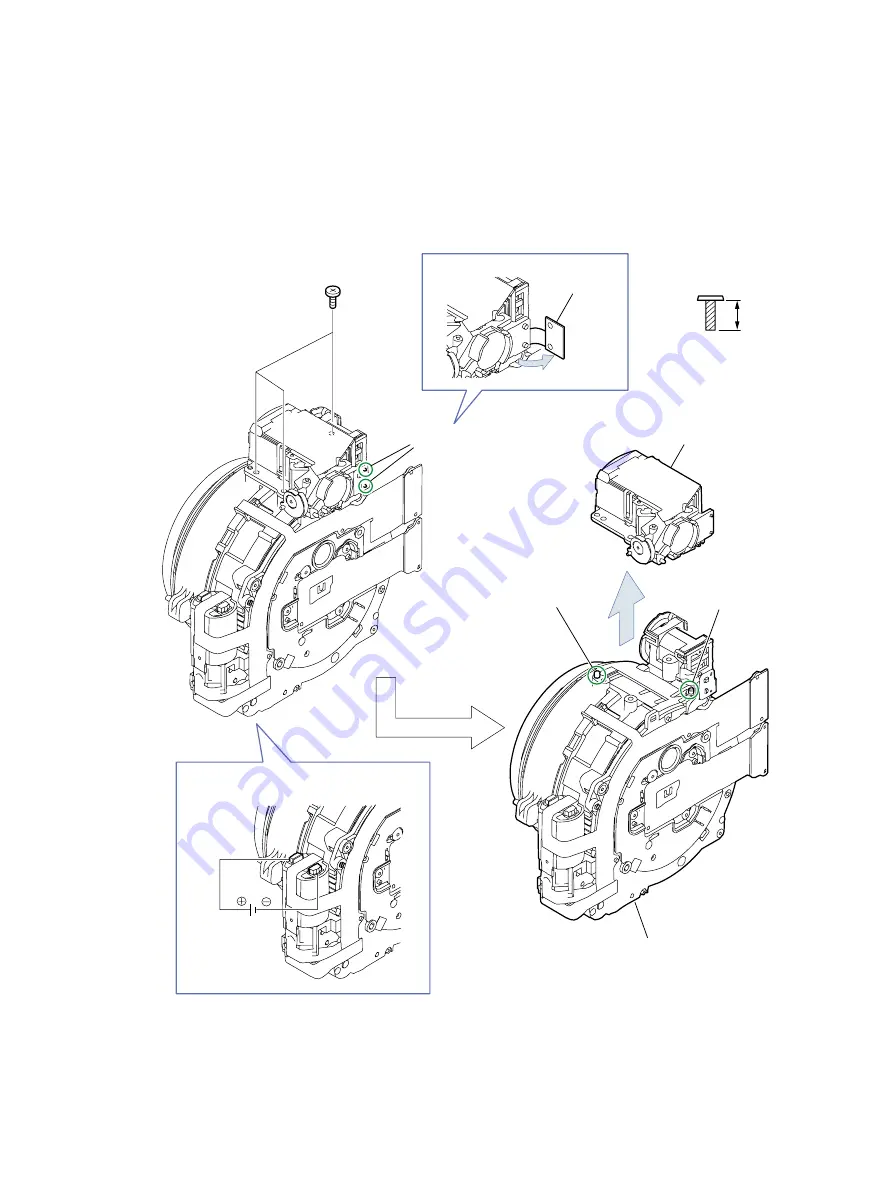
2.26 FINDER UNIT, OPTICAL UNIT

(1) Disengage the two dowels, and remove the portion A.
(2) Remove three screws (

l


×

 3).

(3) Disengage the two dowels, and separate the FINDER UNIT from the OPTICAL UNIT.

<Note on Reassembling>

Apply voltage (DC 2.0V) across the motor terminal to drive the motor until the motor stops and the barrel goes
back to the retracted position, and then install the FINDER UNIT to the OPTICAL UNIT.

CD4-3018-000

3.5mm

SILVER

M1.4

(SELF TAP)

l

(2) -

(3) 

(1)

l

(1)

(3)

FINDER UNIT

(3) OPTICAL UNIT

(1) DC 2.0V

Portion A 

Dowels

Dowel

(3) Dowel

Note on Reassembling

Содержание PowerShot G10 - Digital Camera - Compact

Страница 1: ......

Страница 2: ...rademarks or trademarks of Adobe Systems Incorporated in the United States of America and or other countries All other trademarks product names service marks are generally either registered or unregistered marks of their respective owners Copyright All copyrights in the content of this Service Manual are owned or controlled by Canon Inc You are not permitted to copy reproduce download modify adapt...

Страница 3: ...onnection between Digital Cameras and Printers 24 3 5 Playback Compatibility 25 3 5 1 Still Images 25 3 5 2 Movies 26 3 6 List of Accessory and Its Compatibility 27 3 6 1 Camera 27 4 Accessory Specifications 4 1 New Accessories 29 4 1 1 Waterproof Case WP DC28 29 4 1 2 AC Adapter Kit ACK DC50 31 4 1 3 Battery Charger CB 2LZ CB 2LZE 31 4 1 4 Battery Pack NB 7L 31 4 1 5 Conversion Lens Adapter LA DC...

Страница 4: ...1600 greatly reduce camera shake and subject blur Automatically changes the ISO speed and shutter speed according as the subject movement when the camera detects any face New motion detection technology iSAPS technology enables high speed AF and high definition AE AWB Still Images Face detection function Face detection technology Face Detect AF focuses on the faces in the scene AF frame can be mov...

Страница 5: ...istances Two custom white balance positions allow two white balance settings AF mode allows selection of Single at shooting or Continuous always on AF Continuous shooting AF takes continuous shots while focusing on a moving subject Digital tele converter easily allows telephoto photography as if a tele converter is attached Real time histogram displays the brightness distribution of the scene in r...

Страница 6: ...en when the camera is connected to a printer Exposure Compensation Dial for easily adjusting the exposure compensation ISO Dial enables setting of the optimum ISO speed depending on the scene Control Dial enabling easy control of a various functions Playback button switches between shooting mode and playback mode by one push operation Remote switch enables easy shutter release for photography usin...

Страница 7: ...ble of up to two hours of audio recording Manual adjustment of mic level possible with level meter Multi colored UI UI display available in 26 languages Farsi is added Large capacity new battery NB 7L 1050 mAh Hot shoe enables attaching of external flashes Tele converter lens enables shooting of wide variety of scenes The Field G is the design keyword for this G series camera Quality of material a...

Страница 8: ...water ISO 3200 Color Accent Color Swap Auto P Tv Av M C1 C2 SCN Stitch Assist Movie Portrait Landscape Night Scene Sports Night Snapshot Kids Pets Indoor Foliage Snow Beach Fireworks Aquarium Underwater ISO 3200 Color Accent Color Swap Digital Zoom Still images Movies Approx 4 0x up to approx 20x in combination with the optical zoom Safety Zoom Digital tele converter Still images Movies Approx 4 0...

Страница 9: ...6 2 Exterior 2 1 Exterior Photos 580EX II TC DC58D ...

Страница 10: ...7 2 2 6 view Diagram Unit mm inch Nominal Dimensions 109 1 4 30 77 7 3 06 45 9 1 81 ...

Страница 11: ...8 2 3 Nomenclature ...

Страница 12: ...attached Note Description of the Product Specifications refers to CIPA DCG 002 2007 Specification Guideline for Digital Cameras The measured data with no annotation is measured under normal temperature Shooting Mode Max Wide Angle Max Telephoto Focusing Range 4 from the front of the lens Image Area at the Minimum Focusing Distance Image Magnification Focusing Range 4 from the front of the lens Ima...

Страница 13: ...ngle Not available Focus Control AF System TTL autofocus Manual focus Shooting standby only in movie mode Auto Focus AF Mode Single continuous Servo AF Available Not selectable when AF point zoom is on or FaceSelf Timer is set AF Frame Face Detect 1 2 AiAF 9 points center FlexiZone 1 AF frame can be moved and fixed to specified face 2 If no face is detected AiAF 9 points are used AF Point Zoom Ava...

Страница 14: ...sten Fluorescent Fluorescent H Flash Underwater Custom 1 Custom 2 The colors of faces are evaluated in Face Detect AF Shutter Aperture Shutter Type Mechanical shutter and electronic shutter Aperture Type Iris type Shutter Speeds 1 60 1 4000 sec 15 1 4000 sec Total shutter speed range Shutter speeds vary depending on the shooting modes The following shutter speeds are available in Tv mode or M mode...

Страница 15: ...tact Flash Synchro Shutter Speeds 1 250 sec Maximum synchronized speed Recycling Time Full Flash Depending on the attached speedlite Flash Output Compensation 2 stops in 1 3 stop increments Manual Flash Output Setting 22 levels 580EX II 19 levels 220EX 430EX II Wireless Flash Available On Off only FP Flash Available FE Lock Available Red eye Reduction Available Slow Synchro Available Second curtai...

Страница 16: ... 1 FaceSelf Timer 2 1 Shooting start time 0 10 sec in one second increments 15 20 30 sec and number of shots 1 10 shots in one shot increments can be specified 2 When number of detected faces increases the shutter is released at 2 sec delay However no face is detected for 30 seconds or more the shooting operation starts automatically Remote Shooting Available using supplied software Disp Overlay O...

Страница 17: ...p Audio Specifications Audio Functions Movie sound sound memos also available during rec review sound recorder Quantization Bit Rate Sampling Rate Input Level Adjustment Auto Manual Input Level Indicator 40 0 dB Not available Wind Filter Available Microphone Speaker Available Recording Specifications Still Images Movies Recording Media SD memory card SDHC memory card MultiMediaCard MMCplus card HC...

Страница 18: ...r the recording time reaches one hour Recording Time The approximate recording time on memory cards other than the above can be calculated by using the above figures as a reference and extrapolating accordingly Unit pixels Large 4416 x 3312 Medium 1 3456 x 2592 Medium 2 2592 x 1944 Medium 3 1600 x 1200 Small 640 x 480 Widescreen 4416 x 2480 Unit images Large L Medium 1 M1 Medium 2 M2 Medium 3 M3 S...

Страница 19: ...tput play back the image according to settings RAW Playback CR2 data type Not Available JPEG image recorded simultaneously can be played back Red eye Correction Available i Contrast Available Trimming Available Resize Available Recording pixels after Resize 1600 x 1200 640 x 480 or 320 x 240 pixels Not available for images shot in Widescreen and RAW My Colors Vivid Neutral Sepia Black White Positi...

Страница 20: ...her options except Select images Qty allow only one print per image Print Settings Print Type standard index both Date File No Clear DPOF data can be selected Erasing Specifications Erasing Modes Select image Select range Select by date Select by category Select by folder Select all images The image data in the memory card stored with the design rule for camera file systems for mat can be erased H...

Страница 21: ... Date Function Date Stamp Not available Date Settings Available up to the year 2037 Date Style Year month day month day year or day month year Clock Display Display Items Vertical position hour minute second and year month day Horizontal position hour minute second Also available during playback Display Time 0 10 sec in one second increments 20 30 sec 1 2 3 min Display Colors 4 colors World Time D...

Страница 22: ...Saving Function Auto Power Down when in idle Shooting mode Approx 3 min later Playback mode Approx 5 min later Connection to printer Approx 5 min later During slide show connection to computer The power saving function does not acti vate Display Off 10 20 30 sec 1 2 3 min The Intelligent Orientation Sensor detects the camera being moved and recovers from the display off function Camera Specificati...

Страница 23: ...Remote Switch RS60 E3 High Power Flash HF DC1 USB Port Compact Photo Printers 2 3 SELPHY series Bubble Jet Printers 2 inkjet printer series TV Video Video IN Terminal Audio IN Terminal 1 Also available for purchase separately 2 See the user guide supplied with the printer for more information on the printer and interface cables 3 This camera can also be connected to the CP 10 CP 100 CP 200 CP 300 ...

Страница 24: ...ings are memorized in custom registered condition Colored cells W The settings are retained even when the camera power is turned off 1 Set to the optimum value depending on each shooting mode 2 Fixed to ISO 3200 3 Set to Continuous Shooting LV when Manual Focus setting in practicable shooting mode or fireworks is selected 4 Fixed to Medium 3 1600 x 1200 5 Widescreen is not be set 6 Av Only 7 Tv On...

Страница 25: ...he Print Effect Auto 1 On Off 䕿 䕿 䕿 䕿 䖩 VIVID NR VIVID NR 㽢 㽢 㽢 㽢 䖩 Face brightness adjustment 㽢 㽢 㽢 㽢 䖩 Red eye1 correction 2 㽢 㽢 㽢 䕿 䖩 Red eye2 correction 3 㽢 㽢 㽢 㽢 Setting the Number of Copies 4 䕿 䕿 䕿 䕿 Selecting the Paper Size 5 䕿 䕿 䕿 䕿 Selecting the Paper Type 6 䕿 䕿 䕿 䕿 Setting the Layout Borderless Bordered 䕿 䕿 䕿 䕿 N up 7 㽢 䕿 䕿 䕿 Fixed Sixe 8 㽢 䕿 䕿 䕿 䖩 ID Photo Print 㽢 㽢 㽢 㽢 䖩 20 image index...

Страница 26: ...ut 13Not available when printing without borders 14 Single frame is only possi ble when the camera corre sponds to the Movie print Single frame 15When the print type is set to Index the Date and File Number cannot be set at the same time 16When the print type is set to Standard the File Number cannot be printed Date and File Number Print Date 䕿 䕿 䕿 䕿 䕿 䕿 䕿 䕿 䕿 䕿 File Number 㽢 㽢 㽢 㽢 䕿 䕿 䕿 䕿 䕿 䕿 Set...

Страница 27: ...rint PictBridge Canon Direct Print SELPHY CP series ES series Canon Direct Print PictBridge support CP750 740 730 720 710 530 520 510 500 400 ES2 ES1 ES20 CP600 770 760 PictBridge inkjet printer series Bubble Jet Direct support inkjet printer series Bubble Jet Direct PictBridge support PictBridge Bubble Jet Direct SELPHY DS series Bubble Jet Direct PictBridge support Other manufacturer s Printer P...

Страница 28: ...S40 S30 1 1 1 1 PS Pro1 1 2 2 1 1 2 1 SD ID 600 55 50 40 30a 30 L2 L PS S2 IS PS A400 SD MMC ID 800 IS 700 80 70 60 L3 WIRELESS PS A700 A620 A610 A540 A530 A520 A510 A430 A420 A410 PS S80 2 2 3 3 SD SDHC MMC MMCplus TX1 only ID 900 IS 90 10 L4 PS S3 IS TX1 PS A710 IS A570 IS A560 A550 A460 A450 4 4 4 4 4 4 4 ID 1000 810 IS PS G7 S5 IS PS A640 A630 2 4 2 4 4 4 3 4 3 4 4 SD SDHC MMC MMCplus HC MMCpl...

Страница 29: ... IS SD MMC PS A520 A510 1 1 2 2 ID 800 IS 700 80 70 60 L3 WIRELESS PS S80 except XGA PS A700 A620 A610 A540 A530 A430 A420 A410 2 PS S80 XGA SD SDHC MMC MMCplus TX1 only PS S3 IS except 320 x 240 60fps PS A710 IS A640 A630 A550 A460 A450 5 2 5 5 PS S3 IS except 320 x 240 60fps 5 5 PS S3 IS 320 x 240 60fps ID 1000 900 IS 810 IS 3 90 3 10 3 L4 PS G7 S5 IS TX1 4 PS A570 IS A560 PS TX1 1280 x 720 ID 8...

Страница 30: ...O O CR 560 O O O O O O CB 5L CG 580 O O O O O O CB 2LT CB 2LTE O O CB 2LW 2LWE O O CB 3AH CBK 100 O O O CB 4AH CBK4 200 O O O CBC NB2 O O O O CB 5AH CBK4 300 O O O CB 2LZ CB 2LZE O DC Coupler DR 700 O O DR 20 O O DR 50 O Lens Accessory WC DC58 O O O WC DC58N O O WC DC52A O WC DC58A O WC DC58B O WC DC10 O TC DC52B O TC DC58 O O TC DC58N O O TC DC58A O TC DC58B O TC DC58C O TC DC58D O TC DC10 O O 25...

Страница 31: ...00 RS 60E3 O Cables and Others AVC DC100 O O O O O AVC DC300 O O O O O O O STV 250N O O IFC 200MC O O IFC 200PCS O O IFC 200PCU O O O IFC 300PCU O O IFC 400PCU O O O O O O O O O AD PC98 O O DIF 100 O O O O O O O O O O O DIF 200 O DIF B100 O O O O O O O O O O O DIF B250 O All Weather Case Waterproof Case Waterproof Case Weight WP DC300 O WP DC20 O WP DC40 O WP DC1 O WP DC11 O G7 WP DC21 O G9 WP DC2...

Страница 32: ... 1 seal etc Controls All buttons and controls Printing operation with the Print Share button is not available Supplied Accessories Neck strap wrist strap and silicon grease Remarks Double paned glass lens window with anti reflection coating on both sides diffusion plate detachable Camera Operating Temperatures 0 40 C 32 104 F Dimensions excluding protrusions 150 0 x 106 3 x 116 6 mm 5 91 x 4 19 x ...

Страница 33: ...30 Exterior Unit mm inch 150 0 5 91 106 3 4 19 116 6 4 59 ...

Страница 34: ...ated Input AC 100 240 V 50 60 Hz 14 VA 100 V 19 2 VA 240 V 0 14 A 100 V 0 08 A 240 V Rated Output DC 8 4 V 0 7 A Charging Time Approx 2 hours 20 minutes when charging the NB 7L Charge Indicator Charging Lights orange Charging complete Lights green 2 indicator system Operating Temperatures 0 40 C 32 104 F Dimensions 92 5 x 27 0 x 62 0 mm 3 64 x 1 06 x 2 44 in Weight Approx 92 g Approx 3 2 oz Approx...

Страница 35: ...erior view is omitted Camera mount Bayonet type Thread Diameter 58 mm Max Diameter x Length φ63 8 x 51 6 mm φ2 51 x 2 03 in Weight Approx 30 g 1 06 oz Magnification 1 4x Lens Construction 4 elements in 3 groups Thread Diameter Conversion Lens Adapter LA DC52G is required when attaching 58 mm Max Diameter x Length φ69 0 x 41 2 mm φ2 72 x 1 62 in Weight Approx 140g 4 94 oz Unit mm inch Unit mm inch ...

Страница 36: ...red trademarks or trademarks of Adobe Systems Incorporated in the United States of America and or other countries All other trademarks product names service marks are generally either registered or unregistered marks of their respective owners Copyright All copyrights in the content of this Service Manual are owned or controlled by Canon Inc You are not permitted to copy reproduce download modify ...

Страница 37: ... DIAL UNIT 1 1 3 TOP COVER UNIT TOP FPC ASS Y 1 1 4 FLASH UNIT ST PCB ASS Y 1 1 5 BATTERY FPC ASS Y 1 2 Troubleshooting 2 1 When an Error Code is Displayed 2 2 2 When a Problem Occurs 3 2 3 FUSE 4 2 3 1 DIAGRAM 4 2 3 2 List of Fuses 4 2 3 3 Position of the Fuse 4 ...

Страница 38: ...the video output microphone input audio output signals 7 Controlling the optical unit motor 8 Power supply drive DC DC converter 9 Battery control circuit 1 2 JOG DIAL UNIT 1 Function Buttons of rear side 2 Control Dial 1 3 TOP COVER UNIT TOP FPC ASS Y 1 LED s for Power and Mode and ISO 2 Mode ISO and Power button and Zoom lever and Exposere Dial and Release lever 1 4 FLASH UNIT ST PCB ASS Y 1 Fla...

Страница 39: ...ASS Y E14 UNKNOWN When an error of unknown cause occurs UNKNOWN E16 IMAGING TIME OUT When communication between CPU and peripheral IC is not completed within the specified time during recording using EVF or after completion of recording MAIN PCB ASS Y E23 MEMORY CARD NO SPACE When the Memory Card becomes full during writing of photographed images to Memory Card writing is repeatedly performed with...

Страница 40: ...oes not work MAIN PCB ASS Y TOP COVER UNIT BATTERY FPC ASS Y FU402 BATTERY The image is not displayed on the LCD Monitor MAIN PCB ASS Y LCD UNIT The photograph image is abnormal OPTICAL UNIT MAIN PCB ASS Y The zoom does not function OPTICAL UNIT MAIN PCB ASS Y TOP COVER UNIT The Built in Flash does not fire FLASH UNIT MAIN PCB ASS Y BATTERY FPC ASS Y FU401 FLASH Video output is strange MAIN PCB AS...

Страница 41: ... NO Mounted board Remarks FU401 VD7 2241 251 BATTERY FPC ASS Y Fuse for Flash Line FU402 VD7 3962 001 BATTERY FPC ASS Y Fuse for the battery Line FU402 BATTERY BOX UNIT BATTERY TERMINAL BATT BATTERY FPC ASS Y VBATT for MAIN PCB ASS Y for ST FPC ASS Y VBATT FU401 VBATT BATTERY PCB ASS Y Primary Side FU401 FU402 ...

Страница 42: ...s of America and or other countries All other trademarks product names service marks are generally either registered or unregistered marks of their respective owners Copyright All copyrights in the content of this Service Manual are owned or controlled by Canon Inc You are not permitted to copy reproduce download modify adapt or translate in any way the content of this Service Manual for any purpo...

Страница 43: ...ESSORY SHOE 15 2 14 FINDER DIAL UNIT 16 2 15 LCD UNIT SECTION 17 2 16 LCD UNIT OPERATION PLATE 18 2 17 MAIN PCB ASS Y 19 2 18 CORNER SPACER 20 2 19 BATTERY BLOCK 21 2 20 MAIN CHASSIS UNIT 22 2 21 GYRO FPC ASS Y 23 2 22 LITHIUM 2ND BATTERY MS614SE SII BATEERY BOX UNIT 24 2 23 BATTERY FPC ASS Y 25 2 24 FLASH UNIT 26 2 25 FRONT ST CHASSIS 28 2 26 FINDER UNIT OPTICAL UNIT 30 2 27 FRONT CAP FRONT CAP T...

Страница 44: ...G BLACK CY9 8129 000 Bond 200ml THREE BOND 1401C CY9 8011 000 200g ADHESIVE TAPE SONY T4000 CY4 6012 000 Double sided Tape 0 15mm 6mm 50m roll Fig 1 Precautions on Flash High Voltage Circuit Be sure to read the following precautions before starting the repair work 1 1 Precautions on Flash High Voltage Circuit When separating the FRONT ST CHASSIS be sure to discharge the MAIN CAPACITOR Discharging ...

Страница 45: ...h holes as shown Use them for removal and insertion by inserting the tweezers into them as required Holes The contact piece should face downward Unlocked state Locked state Unlocked state Locked state Unconnected state Connected state 2 Type B The contact piece should face upward Unconnected state Connected state 1 Type A 5 Type E 6 Type F The contact piece should face downward 3 Type C Unconnecte...

Страница 46: ...LATE 1 p 33 2 30 BARRIER PLATE 3 p 34 2 30 BARRIER PLATE SPRING 2 p 34 2 31 BARRIER PLATE 2 p 35 2 31 BARRIER PLATE SPRING 1 p 35 2 32 IRING BARRIER p 37 2 33 GEAR 2 GEAR 3 GEAR 4 GEAR 5 1 p 38 2 34 GEAR 2 GEAR 3 GEAR 4 GEAR 5 2 p 39 2 35 GEAR 2 GEAR 3 GEAR 4 GEAR 5 3 p 40 2 4 REAR COVER SECTION p 6 2 6 FRONT COVER UNIT p 8 2 7 BATTERY COVER SHAFT BATTERY COVER UNIT p 9 2 8 BAYONET UNIT BAYONET TA...

Страница 47: ...4 2 2 BAYONET CAP 1 Rotate the BAYONET CAP in the direction of the arrow while pressing the BAYONET LOCK BUTTON and then remove it 1 1 BAYONET LOCK BUTTON BAYONET CAP ...

Страница 48: ...5 2 3 STRAP BASE 1 Remove two screws a 2 and remove the STRAP BASE CD4 2984 000 3 5mm BLACK M1 7 a 1 STRAP BASE 1 a ...

Страница 49: ...6 2 4 REAR COVER SECTION 1 Remove five screws a 3 b 2 2 Remove the REAR COVER SECTION CD4 2983 000 4 5mm BLACK M1 7 SELF TAP b CD4 2984 000 3 5mm BLACK M1 7 a 2 REAR COVER SECTION b 1 a 1 a 1 b 1 ...

Страница 50: ...7 2 5 REAR COVER UNIT LCD WINDOW 1 Separate the LCD WINDOW from the REAR COVER UNIT 1 1 REAR COVER UNIT LCD WINDOW ...

Страница 51: ...R UNIT 1 Raise the bottom of the FRONT COVER UNIT and remove the three claws 2 Remove the FRONT COVER UNIT 1 FRONT COVER UNIT 1 2 FRONT COVER UNIT Claws Cross section view the claw of FRONT COVER UNIT MAIN BODY Remove ...

Страница 52: ...ve the BATTERY COVER SHAFT in the direc tion of the arrow 3 Remove the BATTERY COVER UNIT Note on Reassembling Install the BATTERY COVER UNIT as shown in the figure 1 BATTERY COVER UNIT 3 BATTERY COVER UNIT BATTERY COVER UNIT 2 BATTERY COVER SHAFT BATTERY COVER SHAFT A pair of tweezers or similar tool Note on Reassembling ...

Страница 53: ...of the arrow 3 Disengage the two dowels and remove the BAYONET UNIT 4 Remove the BAYONET TAPE Note on Disassembling Be careful not to drop the BAYONET TAPE XA1 7170 257 2 5mm SILVER M1 7 c XA4 9170 357 3 5mm SILVER M1 7 SELF TAP d 3 4 3 2 BAYONET UNIT BAYONET TAPE 1 d 1 d 1 c Dowels Plate 3 Dowels ...

Страница 54: ...emove the screw e 1 2 Open the JACK COVER 3 Remove the screw e 1 4 Disengage two dowels and remove the JACK COVER UNIT in the direction of the arrow CD4 2985 000 2 5mm BLACK M1 7 e 3 e 1 e 4 JACK COVER UNIT 2 JACK COVER 4 Dowels ...

Страница 55: ... Remove two screws c 1 f 1 2 Disengage the two connectors 3 Disengage the two dowels and remove the JOG DIAL UNIT XA1 7170 257 2 5mm SILVER M1 7 c CD3 3325 000 2 5mm SILVER M1 7 f 2 3 3 JOG DIAL UNIT 1 c 1 f Dowels Connectors ...

Страница 56: ...e lead wires of the connector because they can break easily Grasp the connector with a pair of tweezers and disconnect it XA1 7170 257 2 5mm SILVER M1 7 c 3 TOP COVER UNIT 3 Dowel 3 Dowel 2 Connector Grasp the connector with a pair of tweezers and disconnect it Note on Disassembling Do not pull the lead wires of the connector because they can break easily 1 c 1 c 1 c ...

Страница 57: ...he DIABOND is applied on the PLATE SPRING Moistening those areas with ethyl alcohol helps to remove the PLATE SPRING Note on Reassembling Apply the DIABOND No 1663G to the positions shown in the figure DIABOND 1663G A pair of tweezers or similar tool DIABOND No 1663G back side 1 PLATE SPRING Note on Reassembling ...

Страница 58: ...gage the dowel and remove the ACCESSORY SHOE Note on Reassembling After tightening the screws g 4 apply the THREE BOND 1401C to positions shown in the figure XA1 3170 407 4 0mm SILVER M1 7 g 2 Dowel Note on Reassembling 2 ACCESSORY SHOE THREE BOND 1401C 1 g ...

Страница 59: ...IAL UNIT by aligning the dowel with the notch 2 Engage two dowels and check each dowel is in the correct position And after that tighten the screw h 1 3 Check that the operations are performed correctly by rotating the dial CD3 2936 000 2 5mm SILVER M1 7 NK GRIP h Procedure for Disassembling Procedure for Reassembling FINDER DIAL UNIT Notch Dowels Dowel Dowels 1 2 3 3 1 1 2 FINDER DIAL UNIT 2 1 h ...

Страница 60: ...el Make sure to handle the flexible board with a pair of tweezers only at the area circled in the diagram because it is thin and easy to damage After connecting the flexible board be sure that it is inserted firmly into the connector XA1 7170 257 2 5mm SILVER M1 7 c XA1 7170 357 3 5mm SILVER M1 7 i 3 Connectors 2 Dowel Flexible board 3 LCD UNIT SECTION Note on Reassembling Note on Reassembling 1 i...

Страница 61: ...o dowels 2 Undo the two linked portions and separate the LCD UNIT from the OPERATION PLATE Note on Reassembling Route the flexible board as shown in the figure 2 OPERATION PLATE 2 LCD UNIT 1 Dowels Flexible boards 2 Linked portions Note on Reassembling ...

Страница 62: ...els and disconnect the connector Then remove the MAIN PCB ASS Y Note on Reassembling Be careful not to catch the flexible board under the MAIN PCB ASS Y 1 2 4 3 i 3 j 4 Dowels Flexible board MAIN PCB ASS Y Connector Connectors 4 Connector XA1 7170 357 3 5mm SILVER M1 7 i XA4 5170 307 3 0mm SILVER M1 7 SELF TAP j Note on Reassembling ...

Страница 63: ...20 2 18 CORNER SPACER 1 Remove the CORNER SPACER Note on Reassembling Align two dowels and install the CORNER SPACER 1 CORNER SPACER CORNER SPACER Dowels Note on Reassembling ...

Страница 64: ...ngage the two dowels and remove the BATTERY BLOCK Note on Disassembling Be careful not to get caught on the flexible boards 2 2 1 2 d f Connector 3 3 Dowels Flexible boards f BATTERY BLOCK Note on Disassembling CD3 3325 000 2 5mm SILVER M1 7 f XA4 9170 357 3 5mm SILVER M1 7 SELF TAP d ...

Страница 65: ...22 2 20 MAIN CHASSIS UNIT 1 Remove two screws h 2 2 Disengage the two dowels and remove the MAIN CHASSIS UNIT CD3 2936 000 2 5mm SILVER M1 7 NK GRIP h 2 MAIN CHASSIS UNIT 2 Dowels 1 h ...

Страница 66: ...GYRO PLATEs 3 Disengage the two dowels and remove the GYRO FPC ASS Y Note on Reassembling Install the GYRO FPC ASS Y as shown in the figure XA4 9170 257 2 5mm SILVER M1 7 SELF TAP k 2 GYRO FPC ASS Y GYRO FPC ASS Y 3 2 3 1 k 1 k GYRO PLATE 2 GYRO PLATE Dowels 2 Dowels Dowels Note on Reassembling ...

Страница 67: ...TTERY MS614SE SII from the BATTERY BOX UNIT Note on Reassembling Make sure that the positive and negative poles face in the right direction BATTERY BOX UNIT LITHIUM 2ND BATTERY MS614SE SII 1 1 Note on Reassembling Make sure that the positive and negative poles face in the right direction ...

Страница 68: ... BATTERY FPC ASS Y do it very carefully so that the flexible board is not ripped Note on Reassembling 1 Attach the DOUBLE SIDED TAPE 10mm 10mm to the position shown in the figure 2 Fold the BATTERY FPC ASS Y and attach it as shown in the figure Bend on this line 2 1 k 1 BATTERY FPC ASS Y BATTERY FPC ASS Y XA4 9170 257 2 5mm SILVER M1 7 SELF TAP k Dowel 1 Dowels Adhesive area DOUBLE SIDED TAPE 10mm...

Страница 69: ...26 2 24 FLASH UNIT 1 Remove two screws d 2 2 Disengage the four dowels and remove the FLASH UNIT XA4 9170 357 3 5mm SILVER M1 7 SELF TAP d 2 FLASH UNIT 2 2 1 d 1 d Dowel Dowels 2 Dowel ...

Страница 70: ...assembling 1 Be careful not to cut the flexible board 2 Engage the two dowels and install the flexible board as shown in the figure Flexible board Flexible board Dowels Note on Reassembling 1 Note on Reassembling 2 ...

Страница 71: ...ws d 2 2 Disengage the three dowels 3 Rotate the FRONT ST CHASSIS in the direction of the arrow A and remove it in the direction of the arrow B 3 A B 3 2 FRONT ST CHASSIS FRONT ST CHASSIS d 1 d 1 XA4 9170 357 3 5mm SILVER M1 7 SELF TAP d Dowels ...

Страница 72: ...h voltage circuit be careful to avoid electric shock and short circuits with other components Note on Reassembling Fold the flexible board and install it as shown in the figure Note Discharge 1kΩ approx 5W Note on Reassembling Bend on this line Bend on this line Bend on this line terminal terminal ...

Страница 73: ...the OPTICAL UNIT Note on Reassembling Apply voltage DC 2 0V across the motor terminal to drive the motor until the motor stops and the barrel goes back to the retracted position and then install the FINDER UNIT to the OPTICAL UNIT CD4 3018 000 3 5mm SILVER M1 4 SELF TAP l 2 3 1 l 1 3 FINDER UNIT 3 OPTICAL UNIT 1 DC 2 0V Portion A Dowels Dowel 3 Dowel Note on Reassembling ...

Страница 74: ...attached to the FRONT CAP TAPE Note on Disassembling Apply ethyl alcohol to the position shown in the figure and remove the FRONT CAP with a pair of tweezers Note on Reassembling Install the FRONT CAP so that the position setting dowels can be aligned as shown in the figure 1 2 1 DC 2 0V FRONT CAP 2 FRONT CAP TAPE A pair of tweezers Ethyl alcohol Position setting dowel Note on Disassembling ...

Страница 75: ...32 2 28 BARRIER CAP 1 Disengage the two dowels one by one and raise the BARRIER CAP 2 Rotate the BARRIER CAP in the direction of the arrow A and remove it 1 1 2 BARRIER CAP A 2 BARRIER CAP Dowels ...

Страница 76: ...pieces Note on Reassembling Install the BARRIER PLATE 1 2 pieces so that the BARRIER PLATE 3 2 pieces is aligned with the positions shown in the figure BARRIER PLATE 1 BARRIER PLATE 1 1 BARRIER PLATE 1 1 BARRIER PLATE 3 BARRIER PLATE 3 Note on Reassembling ...

Страница 77: ...arate the BARRIER PLATE SPRING 2 from the BARRIER PLATE 3 Note on Reassembling Install he BARRIER PLATE 3 and BARRIER PLATE SPRING 2 as shown in the figure BARRIER PLATE 3 BARRIER PLATE SPRING 2 1 BARRIER PLATE 3 BARRIER PLATE SPRING 2 1 BARRIER PLATE SPRING 2 BARRIER PLATE SPRING 2 2 BARRIER PLATE 3 BARRIER PLATE 3 2 Note on Reassembling ...

Страница 78: ...isassembling 1 Remove the BARRIER PLATE 2 2 pieces 2 Rotate the IRING BARRIER in the direction of the arrow slightly and remove the BARRIER PLATE SPRING 1 2 pieces BARRIER PLATE 2 1 BARRIER PLATE 2 1 BARRIER PLATE SPRING 1 BARRIER PLATE SPRING 1 2 2 IRING BARRIER 2 ...

Страница 79: ...as an assembled unit to the OPTICAL UNIT 3 Hook the other side of the BARRIER PLATE SPRING 1 to the projection of the IRING BARRIER 4 Confirm that each part can slide as shown in the figure BARRIER PLATE 2 BARRIER PLATE SPRING 1 BARRIER PLATE SPRING 1 BARRIER PLATE 2 1 BARRIER PLATE SPRING 1 3 4 BARRIER PLATE SPRING 1 3 1 2 2 OPTICAL UNIT IRING BARRIER 3 3 3 ...

Страница 80: ...R 1 Rotate the IRING BARRIER in the direction of the arrow 2 Remove the IRING BARRIER Note on Reassembling Install the IRING BARRIER as shown in the figure IRING BARRIER 1 IRING BARRIER IRING BARRIER 2 Note on Reassembling ...

Страница 81: ... comes fully out 2 Disengage the three dowels and disconnect the three connectors 3 Disengage the five dowels and remove the flexible boards Note on Reassembling Pass the flexible board inside the rib as shown in the figure 1 1 1 DC 2 0V 2 2 3 3 3 2 Note on Reassembling Connector Connectors Dowels Dowels Dowels Flexible boards Flexible board Rib ...

Страница 82: ...screws m 4 2 Separate the FRONT UNIT from the REAR UNIT Note on Disassembling Be careful not to cut the flexible boards FRONT UNIT 2 REAR UNIT 2 m 1 XA4 5140 457 4 5mm SILVER M1 4 SELF TAP m Note on Disassembling Be careful not to cut the flexible boards ...

Страница 83: ...GEAR 5 Note on Reassembling When assembling install GEAR 5 GEAR 4 GEAR 2 and GEAR 3 in that order The four GEARs constitute a set of GEARs When replacing the GEAR replace all of the four GEARs as a set GEAR 3 GEAR 2 GEAR 4 GEAR 5 GEAR 3 1 GEAR 4 3 GEAR 5 4 GEAR 2 2 Note on Reassembling Top Bottom ...

Страница 84: ...1 7 c XA4 9170 357 3 5mm SILVER M1 7 SELF TAP d XA1 7170 357 3 5mm SILVER M1 7 i XA4 9170 257 2 5mm SILVER M1 7 SELF TAP k XA1 3170 407 4 0mm SILVER M1 7 g XA4 5140 457 4 5mm SILVER M1 4 SELF TAP m XA4 5170 307 3 0mm SILVER M1 7 SELF TAP j CD4 2984 000 3 5mm BLACK M1 7 a CD4 3018 000 3 5mm SILVER M1 4 SELF TAP l CD3 2936 000 2 5mm SILVER M1 7 NK GRIP h ...

Страница 85: ...gistered trademarks or trademarks of Adobe Systems Incorporated in the United States of America and or other countries All other trademarks product names service marks are generally either registered or unregistered marks of their respective owners Copyright All copyrights in the content of this Service Manual are owned or controlled by Canon Inc You are not permitted to copy reproduce download mo...

Страница 86: ...Starting up the Adjustment Software 4 3 8 Menu Window 5 3 9 How to Use the Adjustment Software 5 4 Calibration 6 4 1 Calibration 6 5 Adjustment Procedure 10 5 1 IS 1 Adjustment 10 5 1 1 Auto Adjustment 10 5 1 2 Manual Adjustment 12 5 2 IS 2 Adjustment 20 5 3 Optical Unit Adjustment 21 5 4 CCD Adjustment 23 5 5 Pixel Dot Adjustment 26 5 6 Shading Adjustment 28 5 7 Imaging Process Adjustment 30 5 8 ...

Страница 87: ...n saved and then transferred after the part is replaced Blank Adjustment is unnecessary When OPTICAL UNIT is replaced adjust certainly at the procedure as below 1 IS 1 Adjustment 2 Optical Unit Adjustment 3 CCD Adjustment 4 Pixel Dot Adjustment 5 Shading Adjustment 6 Imaging Process Adjustment 7 Color Adjustment 8 Flash Adjustment Adjustment Items IS 1 Adjustment IS 2 Adjustment Optical Unit Adjus...

Страница 88: ... products launched in 2H 2008 Compact Power Adapter CA PS700 Enclosed in AC Adapter Kit ACK DC50 AC Cable Enclosed in AC Adapter Kit ACK DC50 DC Coupler DR 50 Enclosed in AC Adapter Kit ACK DC50 INTERFACE CABLE IFC 400PCU Enclosed in Merchandise Brightness Box CY9 1566 100 200 2 COLLIMATER IS AUTO ADJUSTMENT CY9 1600 000 For 100 240V Color Viewer 5500 K CY9 1562 100 200 2 Color Bar Chart DY9 2002 ...

Страница 89: ...ftware is impossible when the RS 232C TWAIN driver is used 3 3 Canon DCP Connect Installation After downloading and extracting Adjustment Software double click Setup exe Canon DCP Connect Setup exe to install it 3 4 DC Runtime Installation 1 After downloading and extracting DC Runtime double click Setup exe to install it 3 5 Adjustment Software Installation 1 After downloading Adjustment Software ...

Страница 90: ...Connect the Camera s Digital terminal to the PC s USB Port with INTERFACE CABLE IFC 400PCU 6 Turn on the camera while pressing the left side of the cross key and the Print Share button Note Perform the preparation in the following order otherwise the camera won t work properly 3 7 Starting up the Adjustment Software After completing the preparatory steps double click PowerShotG10 exe in the folder...

Страница 91: ...r English or Japanese on top of the Menu Window message to switch over the user interface language Adjustment Menu Calibration For starting click the button related with calibration adjustment Whenever you use your light source for the adjustment for the first time be sure to click the Calibration But ton Quitting the Adjustment Software Click the Exit button Camera Data Saving and Loading Data Tr...

Страница 92: ...he computer 2 Click the OK button 3 When the message on the right appears go to 4 Personal Computer SERVICE MANUAL ADJUSTMENT SOFTWARE Compact Power Adapter CA PS700 AC Cable DC Coupler DR 50 INTERFACE CABLE IFC 400PCU Brightness Box Color Viewer 5500 K Color Bar Chart W 10 Filter 2pcs C 12 Filter FL W Filter ND 4 Filter Light Shielding Cloth 500 500 or larger Reference Camera ...

Страница 93: ... 6 6 1 Attach the two W 10 Filters between the Lens and the Brightness Box Place the camera so that the lens is set against the light source surface of the Brightness Box 2 Cover the camera with a light shielding cloth so that no light enters the camera except from the Brightness Box 3 Set the Brightness Box to the value displayed on the message 4 Click the ADJUST button 7 When the message on the ...

Страница 94: ...UST button 9 When the message on the right appears go to 10 10 1 Attach the Color Bar Chart to the Color Viewer 2 Remove the C 12 and FL W Filter 3 Place the camera so that the Viewing image of the color bar chart is the full of LCD with the ND 4 Filter attached 4 Click the ADJUST button 11 1 Shift a frame on the displayed screen with a mouse to choose a color of color bar 2 Click the Sampling but...

Страница 95: ...9 12 Check Save as the Reference and click the OK button to store the data 13 When the message on the right appears click the FINISH button This ends the Calibration ...

Страница 96: ...llimator The lens attached to the camera moves during the adjustment so be sure to leave about a distance of 1 cm between the camera lens and the collimator lens 2 Adjust the height of the camera and the collimator so that the LED point light source is at the center of the camera s LCD 3 Click the ADJUST button Personal Computer SERVICE MANUAL ADJUSTMENT SOFTWARE Compact Power Adapter CA PS700 AC ...

Страница 97: ...11 4 When the message on the right appears click the FINISH button This ends the IS 1 adjustment ...

Страница 98: ...message on the right appears enter the value written on the Optical Unit Flex in the Focus Sink text box and then click the Update button 2 After the update is complete proceed to step 4 Personal Computer SERVICE MANUAL ADJUSTMENT SOFTWARE Compact Power Adapter CA PS700 AC Cable DC Coupler DR 50 INTERFACE CABLE IFC 400PCU IS Chart 1 Tripod ...

Страница 99: ...enter of the LCD 2 Click the ADJUST button 5 Check if the chart appears in the center on the PC monitor and there is no problem click the ADJUST button 6 Mark the center of the chart on the Monitor and click the ADJUST button 7 Mark the center of the chart on the Monitor and click the ADJUST button IS Chart 1 CAMERA BODY Personal Computer Power Source Tripod 177 3cm ...

Страница 100: ... the ADJUST button and redo the adjustment This step sets the tentative offset value in order to perform the Pitch Gain adjustment 9 When the message on the right appears click the ADJUST button 10 Mark the center of the chart on the Monitor and click the ADJUST button 11 Mark the center of the chart on the Monitor and click the ADJUST button ...

Страница 101: ... the ADJUST button and redo the adjustment This step sets the tentative offset value in order to perform the Yaw Gain adjustment 13 When the message on the right appears click the ADJUST button 14 Mark the center of the chart on the Monitor and click the ADJUST button 15 Mark the center of the chart on the Monitor and click the ADJUST button ...

Страница 102: ...til the distance between the 2 markings becomes 6 scales on chart click the ADJUST button and repeat the steps 13 to 15 17 When the message on the right appears click the ADJUST button 18 Mark the center of the chart on the Monitor and click the ADJUST button 19 Mark the center of the chart on the Monitor and click the ADJUST button ...

Страница 103: ...il the distance between the 2 markings becomes 6 scales on chart click the ADJUST button and repeat the steps 17 to 19 21 When the message on the right appears click the ADJUST button 22 Mark the center of the chart on the Monitor and click the ADJUST button 23 Mark the center of the chart on the Monitor and click the ADJUST button ...

Страница 104: ...rwise change the value of Pitch Offset click the ADJUST button and redo the adjustment 25 When the message on the right appears click the ADJUST button 26 Mark the center of the chart on the Monitor and click the ADJUST button 27 Mark the center of the chart on the Monitor and click the ADJUST button ...

Страница 105: ...ghly in the middle of the 2 markings click the OK button Otherwise change the value of Yaw Offset click the ADJUST button and redo the adjustment 29 When the message on the right appears click the FINISH button This ends the IS 1 adjustment ...

Страница 106: ...e on the right appears click the ADJUST button 3 When the message on the right appears click the FINISH button This ends the IS 2 adjustment Personal Computer SERVICE MANUAL ADJUSTMENT SOFTWARE Compact Power Adapter CA PS700 AC Cable DC Coupler DR 50 INTERFACE CABLE IFC 400PCU ...

Страница 107: ...n the message on the right appears click the ADJUST button 3 When the message on the right appears go to 4 Personal Computer SERVICE MANUAL ADJUSTMENT SOFTWARE Compact Power Adapter CA PS700 AC Cable DC Coupler DR 50 INTERFACE CABLE IFC 400PCU AF Chart 1 Infinity Collimator Tripod ...

Страница 108: ...olor wall or equivalent Adjust the light so that the brightness of the chart will be about EV9 0 The ray of the light should come in at a narrow angle as seen from the chart 2 Adjust the position of the camera finely so that the center of the chart is aligned with the center of the LCD screen 3 Click the ADJUST button 7 When the message on the right appears click the FINISH button This ends the Op...

Страница 109: ...lding Cloth so that no light enters the camera except from the Brightness Box 3 Set the Brightness Box to the value displayed on the message 4 Click the ADJUST button When the adjustment does not work click the Default button Personal Computer SERVICE MANUAL ADJUSTMENT SOFTWARE Compact Power Adapter CA PS700 AC Cable DC Coupler DR 50 INTERFACE CABLE IFC 400PCU Brightness Box Light Shielding Cloth ...

Страница 110: ...e right appears Set the Brightness Box to the value displayed on the message 2 Click the ADJUST button 6 1 When the message on the right appears Set the Brightness Box to the value displayed on the message 2 Click the ADJUST button 7 1 When the message on the right appears Set the Brightness Box to the value displayed on the message 2 Click the ADJUST button ...

Страница 111: ...the camera with the Light Shielding Cloth so that the no light reasons the CCD 2 Click the ADJUST button 10 When the message on the right appears click the FINISH button This ends the CCD Adjustment CAMERA BODY Power Source Personal Computer Light Shielding Cloth ...

Страница 112: ...he ADJUST button Personal Computer SERVICE MANUAL ADJUSTMENT SOFTWARE Compact Power Adapter CA PS700 AC Cable DC Coupler DR 50 INTERFACE CABLE IFC 400PCU Brightness Box Light Shielding Cloth In this adjustment the temperature inside the camera needs to be above a certain temperature If the internal temperature is below this certain temperature the camera will repeat zooming operations to raise the...

Страница 113: ... camera with the Light Shielding Cloth so that the no light reasons the CCD 2 Click the ADJUST button 6 When the message on the right appears click the FINISH button This ends the Pixel Dot Adjustment CAMERA BODY Power Source Personal Computer Light Shielding Cloth ...

Страница 114: ...ness Box 2 Cover the camera with a light Shielding Cloth so that no light enters the camera except from the Brightness Box 3 Set the Brightness Box to the value displayed on the message 4 Click the ADJUST button Personal Computer SERVICE MANUAL ADJUSTMENT SOFTWARE Compact Power Adapter CA PS700 AC Cable DC Coupler DR 50 INTERFACE CABLE IFC 400PCU Brightness Box Light Shielding Cloth Brightness Box...

Страница 115: ...29 4 When the message on the right appears click the FINISH button This ends the Shading Adjustment ...

Страница 116: ...a with a light shielding cloth so that no light enters the camera except from the Brightness Box 3 Set the Brightness Box to the value displayed on the message 4 Click the ADJUST button Personal Computer SERVICE MANUAL ADJUSTMENT SOFTWARE Compact Power Adapter CA PS700 AC Cable DC Coupler DR 50 INTERFACE CABLE IFC 400PCU Brightness Box W 10 Filter 2pcs C 12 Filter FL W Filter Light Shielding Cloth...

Страница 117: ... message on the right appears go to 7 7 1 Remove the W 10 Filters 2 Attach the C 12 and FL W Filter between the Lens and the Brightness Box Place the camera so that the lens is set against the light source surface of the Brightness Box 3 Cover the camera with a light shielding cloth so that no light enters the camera except from the Brightness Box 4 Set the Brightness Box to the value displayed on...

Страница 118: ...32 8 When the message on the right appears click the FINISH button This ends the Imaging Process Adjustment ...

Страница 119: ...ng image of the color bar chart is the full of LCD with the ND 4 Filter attached 3 Click the ADJUST button Color AdjustmentPersonal Computer SERVICE MANUAL ADJUSTMENT SOFTWARE Compact Power Adapter CA PS700 AC Cable DC Coupler DR 50 INTERFACE CABLE IFC 400PCU Color Viewer 5500 K Color Bar Chart ND 4 Filter Color Viewer Color Bar Chart Personal Computer CAMERA BODY Power Source Stand ND 4 Filter ...

Страница 120: ...ence Camera 10 Ave_Cb Reference Camera 10 6 1 Confirm to see that the image on the PC monitor satisfies the specifications 2 If the image on the PC monitor does not satisfy the specifications change the data using UP DOWN button or change the data directly by typing the data in the text box Then click the Update button If these data are within specifications click the OK button 7 When the message ...

Страница 121: ... Disconnect the reference camera from the PC and display the Gray jpg image in PLAY mode 1 Click the LCD button 2 1 Compare the image with that of the reference camera If it has a different color tint adjust it by repeating clicking the Yellow Blue button and the Update button alternately 2 Click the FINISH button This ends the LCD Adjustment Personal Computer SERVICE MANUAL ADJUSTMENT SOFTWARE Co...

Страница 122: ...42 3cm away from the front of the camera finder 2 Make the room as dark as a darkroom 3 Click the ADJUST button Personal Computer SERVICE MANUAL ADJUSTMENT SOFTWARE Compact Power Adapter CA PS700 AC Cable DC Coupler DR 50 INTERFACE CABLE IFC 400PCU 18 Gray Chart Tripod Personal Computer Power Source 18 Gray Chart 42 3cm CAMERA BODY Tripod ...

Страница 123: ...37 4 When the message on the right appears click the FINISH button This ends the Flash Adjustment ...

Страница 124: ...38 5 11 Checking of sound recording output It is not required to adjust the recording output volume etc of sound Check the camera if the sound is recorded play backed properly ...

Страница 125: ...enerally either registered or unregistered marks of their respective owners Copyright All copyrights in the content of this Service Manual are owned or controlled by Canon Inc You are not permitted to copy reproduce download modify adapt or translate in any way the content of this Service Manual for any purpose other than the purpose contemplated herein without prior written consent of Canon Inc D...

Страница 126: ...SS Y Secondary Side 2 3 ST FPC ASS Y Primary Side 2 4 OPT FPC ASS Y Primary Side 2 5 AF FPC ASS Y Primary Side 2 6 SH FPC ASS Y Primary Side 2 7 IS FPC ASS Y Primary Side 2 8 GY FPC ASS Y Primary Side 2 9 DIAC FPC ASS Y Primary Side 2 10 RLS FPC ASS Y Primary Side 2 11 BATT FPC ASS Y Primary Side ...

Страница 127: ... FPC MAIN PCB ASS Y JOG DIAL UNIT FLASH UNIT GYRO FPC ASS Y BATTERY FPC ASS Y Exposure LED ISO LED ST FPC OPTICAL UNIT LCD UNIT CN1003 IC1006 IC1007 IC1003 IC601 FU402 CN402 CN401 CN251 CN3501 CN560 CN1002 MEMORY CARD CONNECTOR MEMORY CARD CN4601 A V OUT CN1001 DIGITAL CN1006 REMOTE Metal contact Pins face down Metal contact Pins face up Metalcontact Metalcontact SPEAKER UNIT Direct Solder Direct ...

Страница 128: ...7 IC1003 SR1001 L 6 6 4 L663 D675 D676 D677 Q1001 Q656 RA1010 RA1011 R606 R1109 R1110 R621 R622 R623 R624 R631 R632 R633 R634 R635 R636 R637 R641 R642 R643 R644 R645 R646 R647 R4603 R4604 R657 R666 R667 R676 R677 R1015 R1016 R1018 R1022 R1025 R1026 R1041 R1042 L1001 CN1002 L661 L662 L665 L666 L667 C1999 R4605 IC601 CN1001 C611 R615 C615 CN4601 FP1001 FP1002 FP1003 FP4601 FP601 FP603 FP604 FP671 FP...

Страница 129: ...C2004 IC3201 IC4501 IC1002 IC1004 IC1008 IC2003 L3201 L2001 L2002 L4501 IC1009 Q1007 D1001 Q1002 Q503 Q1004 Q1005 Q1006 IC4601 IC1005 IC2001 IC2005 IC501 IC502 Q501 Q504 Q1003 RA3001 RA3002 RA3003 RA3005 RA3202 RA1009 RA1012 RA3201 RA1004 RA1005 RA1006 RA1007 RA1013 RA1014 RA1016 R3224 R3225 R3226 R3227 R3228 R3229 R3230 R3231 R1101 R1103 R1105 R1106 R1107 R1108 R1111 R4004 R4601 R4602 R501 R502 R...

Страница 130: ...1 D 5 6 2 T560 Q560 Q56 1 L5 6 0 R562 R 5 6 3 R 5 6 6 C 5 60 C 5 6 1 C 5 6 3 C 5 6 4 R 5 6 5 R 5 6 4 C 5 6 2 R 5 6 1 R560 Q 5 6 2 C N 5 6 0 FP563 FP561 FP562 FP560 NOTE NOTE The ST FPC PCB ASS Y Secondary Side is intentionally omitted because of no parts mounted on this side ...

Страница 131: ...OPT FPC ASS Y Primary Side LED3501 LED3502 LED3503 CN3501 CN3502 C N 3 5 0 3 C N 3 5 0 4 CN3505 CN3506 PS3501 P S 3 5 0 2 PS3503 NOTE NOTE The OPT FPC ASS Y Secondary Side is intentionally omitted because of no parts mounted on this side ...

Страница 132: ... CANON INC 2008 02 OCTOBER 2008 2 5 AF FPC ASS Y Primary Side P S 3 7 0 1 NOTE NOTE The AF FPC ASS Y Secondary Side is intentionally omitted because of no parts mounted on this side ...

Страница 133: ... CANON INC 2008 02 OCTOBER 2008 2 6 SH FPC ASS Y Primary Side TH3601 NOTE NOTE The SH FPC ASS Y Secondary Side is intentionally omitted because of no parts mounted on this side ...

Страница 134: ... CANON INC 2008 02 OCTOBER 2008 2 7 IS FPC ASS Y Primary Side IC3801 IC3802 NOTE NOTE The IS FPC ASS Y Secondary Side is intentionally omitted because of no parts mounted on this side ...

Страница 135: ... CANON INC 2008 02 OCTOBER 2008 2 8 GY FPC ASS Y Primary Side SR3901 SR3902 C3902 C3901 NOTE NOTE The GY FPC ASS Y Secondary Side is intentionally omitted because of no parts mounted on this side ...

Страница 136: ...OCTOBER 2008 2 9 DIAC FPC ASS Y Primary Side LED301 LED302 SW 3 0 1 D301 D302 D303 D304 D 3 0 5 D 3 0 6 D 3 0 7 NOTE NOTE The DIAC FPC ASS Y Secondary Side is intentionally omitted because of no parts mounted on this side ...

Страница 137: ... Q201 L 2 0 1 L202 L 2 0 3 L204 R201 R 2 0 3 SW202 C201 D 2 0 1 Q 2 0 3 S W 2 0 1 L205 CN201 ZNR201 R 2 1 0 R211 ZNR202 ZNR203 ZNR204 ZNR205 ZNR206 ZNR207 R205 R206 R207 R208 R209 R212 ZNR208 CP201 NOTE NOTE The RLS FPC ASS Y Secondary Side is intentionally omitted because of no parts mounted on this side ...

Страница 138: ...INC 2008 02 OCTOBER 2008 2 11 BATT FPC ASS Y Primary Side CN401 CN402 CN403 BAT401 C401 FU401 FU402 NOTE NOTE The BATT FPC ASS Y Secondary Side is intentionally omitted because of no parts mounted on this side ...

Страница 139: ...product names service marks licensed to Canon inc by any of its affiliate or subsidiary are registered or unregistered marks of Canon inc or such affiliate or subsidiary in Japan and or other countries Adobe the Adobe logo Acrobat the Acrobat logo and Reader are either registered trademarks or trademarks of Adobe Systems Incorporated in the United States of America and or other countries All other...

Отзывы: