


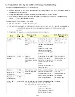


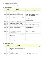


1-3. Service Call Error (by Cyclic Blinking of Alarm and Power LEDs) Troubleshooting
Service call errors are indicated by the number of cycles the Alarm and Power LEDs blink, and the corresponding
error code with the message, "Printer error has occurred. Turn off power then back on again. If problem persists,
see the manual." is displayed on the LCD.
1) Check each point in "Check points & Solution," and perform the solution if it applies.
2) When no solution in "Check points & Solution" is effective, then replace the part listed under "Parts to that
are likely to be faulty" one by one from the one most likely to be faulty. The parts are listed in the order of
likeliness to be faulty.
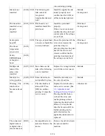
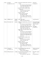
ADF is too
long.
long. Check document
in ADF, then press
[OK] and redo
operation..
ADF, and press the OK
button.
Double-sided
printing not
available with
the paper in the
ADF.
[2804]
--- Document size not
suitable for duplex
scanning. Press [OK]
to cancel operation
and eject document.
Remove the paper from the
ADF, and press the OK
button.
- DF unit
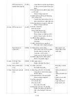
Time-out for
the scanner
device.
[2700]
--- Timeout error has
occurred. Press [OK].
The buffer became full in
the middle of scanning
operation, and 60 minutes
have elapsed since then,
making re-scanning
unstable. Press the OK
button to clear the error.
Premium
Contents print
error.
[4100]
--- Cannot print the data. Non-genuine ink tanks are
installed. Install the
supported (Canon-genuine)
ink tanks.
- Ink tank
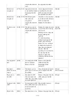
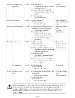
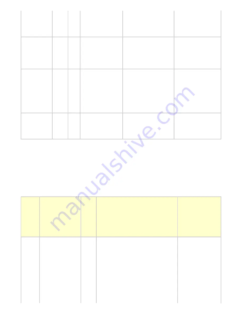
Cycles
of
blinking
of
Alarm
and
Power
LEDs
Error
Error
code
Check points & Solution
Parts that are likely
to be faulty (listed
in the order of
likeliness to be
faulty)
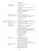
2 times
Carriage error
[5100]
(1) Smearing or scratches on the carriage
slit film:
Clean the film using lint-free paper.
(2) Foreign material that obstructs the
carriage movement:
Remove foreign material.
(3) Ink tank conditions:
Re-set the ink tanks.
(4) Cable connection:
- CR FFC (J500, J501, J502, etc.)
- Timing slit strip film
- Carriage unit
- Logic board ass'y
- Carriage motor
8 / 76
Содержание PIXMA MX882 Series
Страница 32: ...8 Remove the main case no screws 28 76...
Страница 35: ...4 Remove the LCD ass y no screws 31 76...
Страница 42: ...6 ASF unit removal 1 Remove 1 screw from the left plate and 2 screws from the right plate 38 76...
Страница 55: ...2 Service Tool functions Service Tool screen Version 2 000 51 76...
Страница 56: ...52 76...
Страница 67: ...63 76...
Страница 74: ...4 2 Integrated Inspection Pattern Print Print sample...
Страница 75: ...4 3 Ink Absorber Counter Value Print Print sample 4 VERIFICATION AFTER REPAIR...
Страница 78: ......


