


CHAPTER 4 IMAGE FORMATION SYSTEM
COPYRIGHT © 1999 CANON INC. CANON NP6512/6612/7120/7130/7130F REV.0 AUG. 1999 PRINTED IN JAPAN (IMPRIME AU JAPON)
4-6
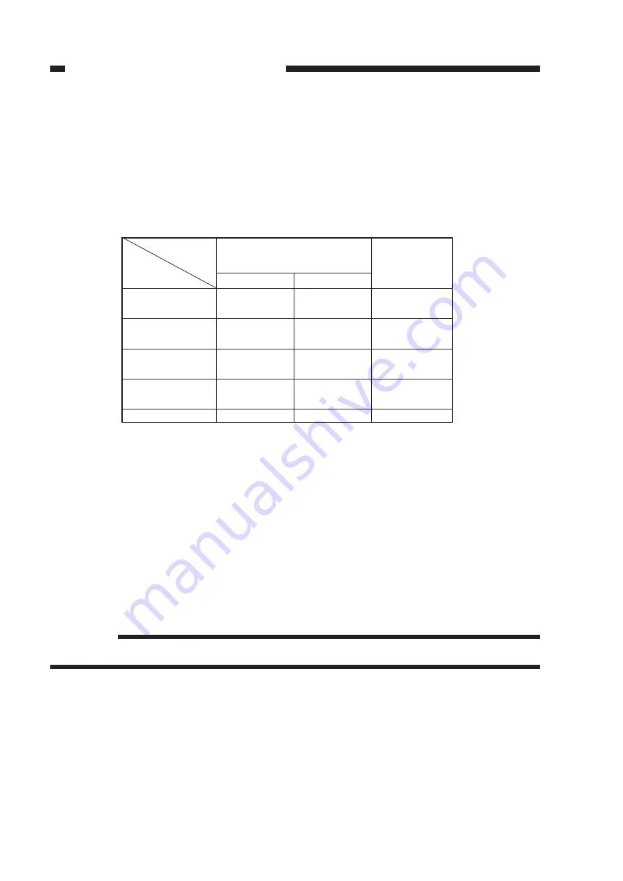
Table 4-102 Relationship between DC Bias Output and Signal
DC bias ON signal
(8-bit signal communication)
bit0
bit1
1
–
1
0
1
1
0
–
0
0
PR_DC_ON
(J103-5)
0
1
1
0
1
DC bias ON
(image area)
DC bias ON
(non-image area)
*1
DC bias ON
(non-image area)
*2
DC bias ON
(APVC)
DC bias OFF
b.
Controlling the DC Bias to a Specific Voltage/Current
The DC bias applied to the primary charging roller is controlled by the microprocessor (Q900)
on the composite power supply PCB so that it remains a specific level.
When a DC bias is generated, the microprocessor (Q900) on the composite power supply PCB
detects the DC voltage monitor signal (PDC_S), compares its level against the reference level, and
varies the DC bias control signal (PDC_PWM) according to the difference so as to ensure that it
remains specific level.
Reference:
The DC bias control signal varies its pulse duty ratio to change the level of the DC bias.
2.
Operations
a.
Turning On and Off the DC Bias
The DC bias applied to the primary charging roller is turned on or off by the serial communica-
tion signal and the primary charging bias ON signal (PR_DC_ON) from the DC controller PCB.
When the Copy Start key is pressed, the DC bias ON signal (serial) and the primary charging
bias ON signal (PR_DC_ON) are sent. The microprocessor (Q900) on the composite power supply
PCB generates the DC bias control signal (PDC_PWM) based on the combination of the serial
signal and the PR_DC_ON signal, applying a DC bias to the primary charging roller.
*1: Area between sheets
*2: Cleaning area by transfer / trailing edge area
Содержание NP6412
Страница 6: ......
Страница 12: ......
Страница 34: ......
Страница 46: ......
Страница 48: ......
Страница 92: ......
Страница 144: ......
Страница 176: ......
Страница 178: ......
Страница 192: ......
Страница 194: ......
Страница 220: ......
Страница 222: ......
Страница 256: ......
Страница 258: ......
Страница 282: ......
Страница 284: ......
Страница 286: ......
Страница 384: ......
Страница 388: ......
Страница 402: ...A 18 COPYRIGHT 1999 CANON INC CANON NP6512 6612 7120 7130 7130F REV 0 AUG 1999 PRINTED IN JAPAN IMPRIME AU JAPON ...
Страница 412: ...A 28 COPYRIGHT 1999 CANON INC CANON NP6512 6612 7120 7130 7130F REV 0 AUG 1999 PRINTED IN JAPAN IMPRIME AU JAPON ...
Страница 414: ......
Страница 424: ......
Страница 426: ...0899AB1 51 1 PRINTED IN JAPAN IMPRIME AU JAPON This pubication is printed on 70 reprocessed paper ...
Страница 430: ......
Страница 432: ......
Страница 434: ......
Страница 446: ...CHAPTER 2 STANDARDS AND ADJUSTMENTS 2 10 7 Remove the four screws 7 and detach the lens cover 8 Figure 2 15 7 7 8 ...
Страница 456: ...CHAPTER 2 STANDARDS AND ADJUSTMENTS 2 20 9 Detach the pulley clip 16 from the cable drive pulley 1 Figure 2 33 1 16 ...
Страница 484: ......
Страница 492: ......
Страница 502: ......
Страница 506: ......
Страница 516: ......
Страница 518: ...0899AB1 11 1 PRINTED IN JAPAN IMPRIME AU JAPON This pubication is printed on 70 reprocessed paper ...
Страница 599: ...PRINTED IN JAPAN IMPRIME AU JAPON ...


