(8/58)
2. ADJUSTMENT / SETTINGS
2-1. Service
Mode
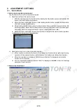
< Service mode operation procedures >
Use the Service Tool on the connected computer.
1) Start the machine in the service mode.
i.
With the machine power turned off, while pressing the Stop button, press and hold the ON
button. (DO NOT release the buttons).
ii.
When the Power LED lights in green, while holding the ON button, release the Stop button.
(DO NOT release the ON button.)
iii. While holding the ON button, press the Stop button 2 times, and then release both the ON
and Stop buttons. (Each time the Stop button is pressed, the Alarm and Power LEDs light
alternately, Alarm in orange and Power in green, starting with Alarm LED.)
iv. When the Power LED lights in green, the machine is ready for the service mode operation.
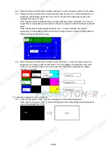
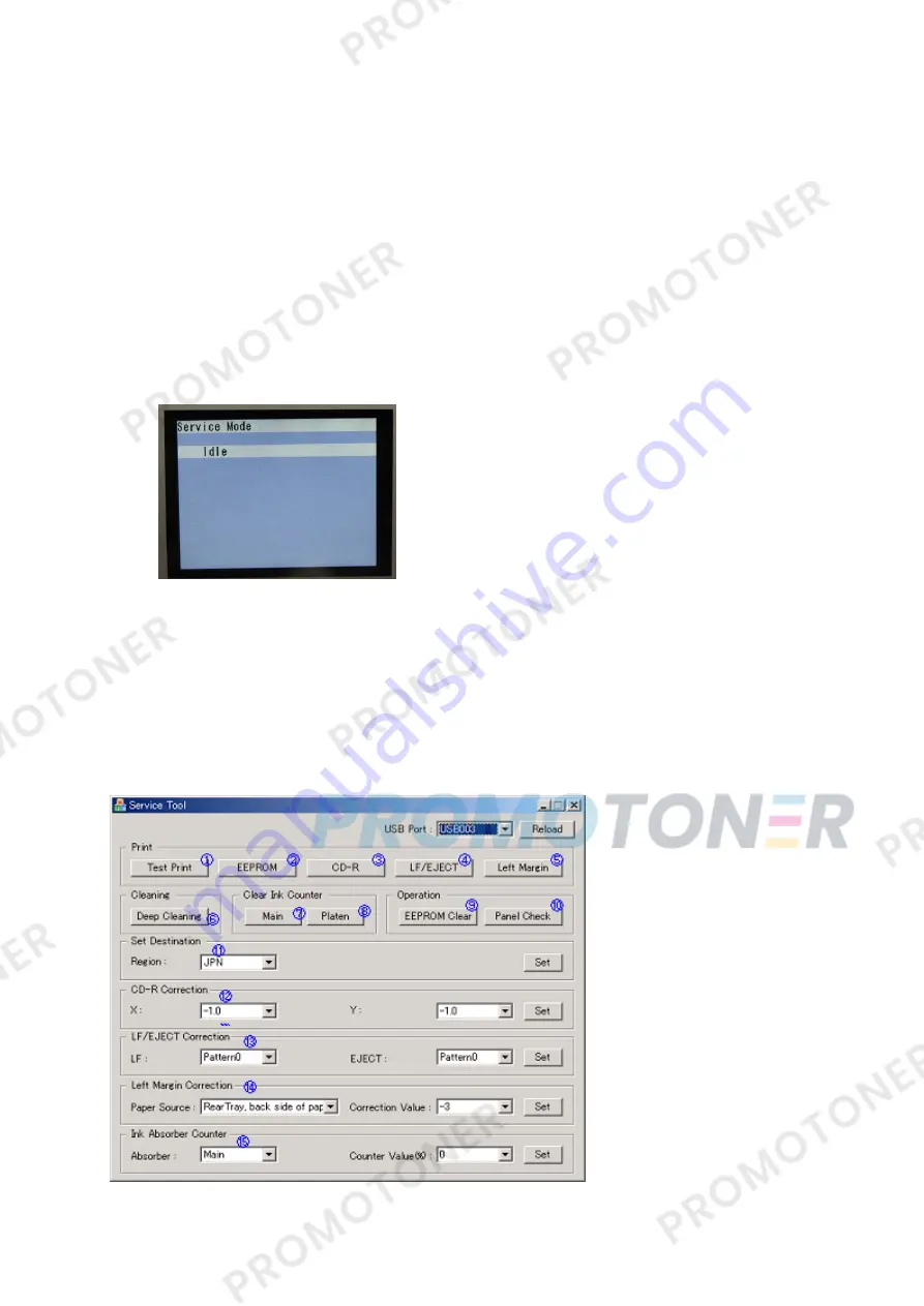
- LCD ready for the service mode operation:
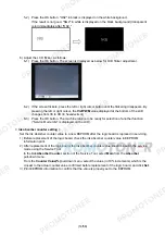
2) Start the Service Tool on the connected computer.
i.
When a button is clicked in the Service Tool dialog box, that function is performed. During
operation of the selected function, all the Service Tool buttons are dimmed and inactive.
ii
When the operation is completed, "A function was finished." is displayed, and another
function can be selected.
iii
If a non-supported function is selected, "Error!" is displayed. Click
OK
in the error message
dialog box to exit the error.
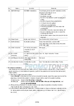
< Service Tool Functions >
Содержание MP540
Страница 11: ...11 58...
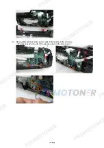
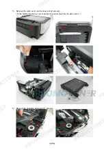
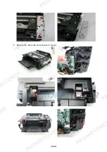
Страница 19: ...19 58 7 Remove the main case and sub case 1 screw...
Страница 27: ...27 58 3 EXTERNAL VIEW PARTS LIST FIGURE 1 PACKING CONTENTS PRINT HEAD...
Страница 29: ...29 58 FIGURE 2 AC ADAPTER...
Страница 31: ...31 58 FIGURE 3 EXTERNAL COVERS SCANNER UNIT...
Страница 33: ...33 58 FIGURE 4 DOCUMENT PRESSURE PLATE UNIT...
Страница 35: ...35 58 FIGURE 5 OPERATION PANEL UNIT...
Страница 37: ...37 58 FIGURE 6 MAIN CASE FRONT DOOR UNIT...
Страница 39: ...39 58 FIGURE 7 BOTTOM CASE INK ABSORBER...
Страница 41: ...41 58 FIGURE 8 LOGIC BOARD ASS Y PE SENSOR BOARD ASS Y...
Страница 43: ...43 58 FIGURE 9 SHEET FEED UNIT...
Страница 45: ...45 58 FIGURE 10 CARRIAGE UNIT PRESSURE ROLLER UNIT...
Страница 47: ...47 58 FIGURE 11 PLATEN UNIT SPUR UNIT...
Страница 49: ...49 58 FIGURE 12 PURGE DRIVE SYSTEM UNIT SWITCH SYSTEM UNIT...
Страница 51: ...51 58 FIGURE 13 OPTION CONSUMABLES...
Страница 53: ...53 58 FIGURE 14 TOOL...
Страница 55: ...55 58 REFERENCE PRINTER UNIT...


