background image

(21/58) 

Service part 

Notes on replacement

*1


Adjustment / settings 

Operation check 

Platen unit 


After replacement:


1) Perform LF / Eject correction in 

the service mode.   

- EEPROM information print 

- Service test print 

Spur unit 

- DO NOT contact the spur 

edges. 

After replacement:


1) Check the ink system function. 
2) Perform LF / Eject correction in 

the service mode.   

- EEPROM information print 

- Service test print 


Purge drive 

system unit 


After replacement:


1) Confirm the purging operation 

and the machine operation. 

- Service test print 

Carriage rail and 

main chassis 

Idler pulley 

parallel pin 

Easy-Scroll 

Wheel base 

APP code wheel 

gear shaft 


At replacement:


1) Apply grease to the sliding 

portions.


- Service test print 

Document cover 

unit 

Scanner unit 


At replacement:


1) Confirm the document pressure 

sheet position. 

- Service test print 

Panel board 

ass'y 

LCD unit 

- Be cautious not to scratch 

or damage the LCD cable.

At replacement:


1) Perform button and LCD test. 

- Service test print 

Timing slit strip 

film 


Timing slit disk 

feed film 

- Upon contact with the film, 

wipe the film with ethanol. 

- Confirm no grease is on 

the film. (Wipe off any 

grease thoroughly with 

ethanol.) 

- Do not bend the film 

After replacement:


1) Perform print head alignment in 

the user mode. 

2) Perform LF / Eject correction in 

the service mode.   


- EEPROM information print 

- Service test print 


Print head 


After replacement:


1) Perform print head alignment in 

the user mode. 

- Service test print 

*1:  General notes: 
 

- Make sure that the flexible cables and wires in the harness are in the proper position and 

connected correctly. 


- Do not drop the ferrite core, which may cause damage. 


- Protect electrical parts from damage due to static electricity. 


- Before removing a unit, after removing the power cord, allow the machine to sit for approx. 1 

minute (for capacitor discharging to protect the logic board ass'y from damages). 


- Do not touch the timing slit strip film, and timing slit disk feed film. No grease or abrasion is 

allowed. 


- Protect the units from soiled with ink. 


- Protect the housing from scratches. 


- Exercise caution with the screws, as follows: 


i.  The screws of the paper feed motor may be loosened only at replacement of the paper 

feed motor unit (DO NOT loosen them in other cases).  


ii.  Before loosening the 3 screws that fix the carriage rail to the main chassis, mark the 

screw positions so that the carriage rail will be re-attached to the main chassis in its 

Содержание MP540

Страница 1: ...1 58 MP540 MP545 SIMPLIFIED SERVICE MANUAL 1 LIST OF ERROR DISPLAY 2 ADJUSTMENT SETTINGS 3 EXTERNAL VIEW PARTS LIST QY8 13CA 000 Rev 00 July 31 2008 Canon Inc...

Страница 2: ...ce Set the paper in the cassette and press the OK button Note Only plain paper can feed from the cassette Paper jam 1300 Paper jam in the rear guide 1303 The paper is jammed Clear the paper and press...

Страница 3: ...or longer to disable the function to detect the remaining ink amount After the operation it is recorded in the machine EEPROM that the function to detect the remaining ink amount was disabled Ink tan...

Страница 4: ...ror 5100 An error occurred in the carriage encoder signal 1 Smearing or scratches on the carriage slit film clean the timing slit film 2 Foreign material or paper debris that obstructs the carriage mo...

Страница 5: ...ture exceeded the specified value 1 Print head condition 2 Cable connection 3 Part replacement Print head Logic board 9 times EEPROM error 6800 6801 A problem occurred in reading from or writing to th...

Страница 6: ...oreign material 2 Part replacement Purge drive system unit ASF unit Scanner error 5011 An error occurred in the scanner 1 Document pressure sheet conditions 2 Cable connection 3 Part replacement Docum...

Страница 7: ...the print head temperature exceeds the specified limit an intermission is inserted during printing Restrictions on paper The current paper cannot be set Change the size and type Re select the support...

Страница 8: ...button is pressed the Alarm and Power LEDs light alternately Alarm in orange and Power in green starting with Alarm LED iv When the Power LED lights in green the machine is ready for the service mode...

Страница 9: ...ette and click OK EEPROM information print Model name ROM version Ink absorber counter value ink amount in the ink absorber Print information Error information etc 3 CD R CD R check pattern print Not...

Страница 10: ...below 14 Left Margin Correction Left margin correction value setting Not used 15 Ink Absorber Counter Ink absorber counter setting See Ink absorber counter setting below LF Eject correction After rep...

Страница 11: ...11 58...

Страница 12: ...ation panel 3 Only one button should be pressed at one time If 2 or more buttons are pressed at the same time only one of them is considered to be pressed and the other buttons are ignored The LCD is...

Страница 13: ...ps rotated counterclockwise over 1 round 16 steps the color of segment s corresponding to the extra number of steps returns to green starting with the Start segment in the figure below 4 4 When the Ea...

Страница 14: ...r selection of another function Service Mode Idle is displayed on the LCD Ink absorber counter setting Set the ink absorber counter value to a new EEPROM after the logic board is replaced in servicing...

Страница 15: ...ded to perform deep cleaning only when necessary Manual print head alignment Perform via the machine operation panel or from the MP driver Maintenance tab Set 3 sheets of plain paper A4 or Letter in t...

Страница 16: ...document cover removal 1 Remove the cassette and open the front door 2 Pull up the document cover to remove it then remove the rear top cover and the middle frame 4 screws 3 Remove the side cover R 2...

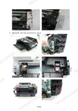
Страница 17: ...17 58 4 Remove the scanner cable panel cable FB encoder cable and core The core is fixed on the rib of the sub case back of the main case...

Страница 18: ...18 58 5 Remove the side cover L and scanner unit 2 screws While holding the scanner unit separate the scanner stay from the side cover L 6 Remove the operation panel unit 11 screws...

Страница 19: ...19 58 7 Remove the main case and sub case 1 screw...

Страница 20: ...lignment and LCD language setting in the user mode EEPROM information print Service test print Printing via USB connection Copying Direct printing from a digital camera PictBridge Absorber kit After r...

Страница 21: ...film Wipe off any grease thoroughly with ethanol Do not bend the film After replacement 1 Perform print head alignment in the user mode 2 Perform LF Eject correction in the service mode EEPROM informa...

Страница 22: ...feed motor may be loosened only at replacement of the paper feed motor unit DO NOT loosen them in other cases 4 Document pressure sheet sponge sheet replacement 1 Peel off the cover sheet from the dou...

Страница 23: ...ing without a document on the platen glass 5 Ink absorber counter setting Before replacement of the logic board check the ink absorber counter value and register it to the replaced new logic board The...

Страница 24: ...surface where the carriage unit slides 3 Floil KG107A 360 to 440 4 Carriage rail The surface where the carriage unit slides 4 Floil KG107A 360 to 440 5 Main chassis The surface where the carriage uni...

Страница 25: ...25 58 2 Operation panel Easy Scroll Wheel No Part name Where to apply grease oil Drawing No Grease Grease amount mg 8 Easy Scroll Wheel base Easy Scroll Wheel sliding portions 8 Floil KG107A 9 to 18...

Страница 26: ...rom the machine and left alone by itself ink the pigment based black ink in particular is likely to dry For this reason keep the print head installed in the machine even during transportation b Secure...

Страница 27: ...27 58 3 EXTERNAL VIEW PARTS LIST FIGURE 1 PACKING CONTENTS PRINT HEAD...

Страница 28: ...CORD POWER 220V 240V EUM EMB ASA MY 3 QH2 2719 000 1 CORD POWER 100V 120V 3 QK1 0776 000 1 CORD POWER 220V 240V AU 3 QK1 2017 000 1 CORD POWER 100V 120V TW 3 QK1 3048 000 1 CORD POWER 120V 240V LAM C...

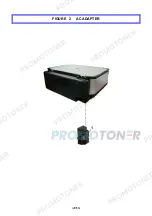
Страница 29: ...29 58 FIGURE 2 AC ADAPTER...

Страница 30: ...30 58 LIST OF FIGURE 2 FIGURE KEY No PART NUMBER RANK QTY DESCRIPTION REMARKS 2 1 QK1 4965 000 1 AC ADAPTER 100V 240V 50 60HZ...

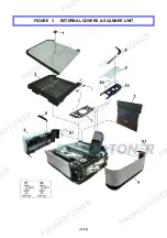
Страница 31: ...31 58 FIGURE 3 EXTERNAL COVERS SCANNER UNIT...

Страница 32: ...3683 000 1 SIDE COVER L UNIT 6 QC2 7841 000 1 STAY SCANNER 7 QL2 2602 000 1 COVER OPERATION PANEL CA AU ASA 7 QL2 2603 000 1 COVER OPERATION PANEL JP 7 QL2 2604 000 1 COVER OPERATION PANEL LAM GB EUM...

Страница 33: ...33 58 FIGURE 4 DOCUMENT PRESSURE PLATE UNIT...

Страница 34: ...34 58 LIST OF FIGURE 4 FIGURE KEY No PART NUMBER RANK QTY DESCRIPTION REMARKS 4 1 QM3 3692 000 1 DOCUMENT COVER UNIT 2 QC2 7863 000 2 HINGE 3 QC2 9324 000 1 SHEET DOCUMENT PRESSURE...

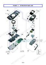
Страница 35: ...35 58 FIGURE 5 OPERATION PANEL UNIT...

Страница 36: ...Y POWER 7 QC2 7876 000 1 KEY START 8 QC2 8026 000 1 BASE JOG WHEEL 9 QM3 3709 000 1 PANEL BOARD ASS Y 10 QM3 3696 000 1 LCD UNIT 11 QC2 9308 000 1 LABEL PRODUCT NAME MP540 11 QC2 9309 000 1 LABEL PROD...

Страница 37: ...37 58 FIGURE 6 MAIN CASE FRONT DOOR UNIT...

Страница 38: ...URE 6 FIGURE KEY No PART NUMBER RANK QTY DESCRIPTION REMARKS 6 1 QM3 3641 000 1 REAR GUIDE UNIT 2 QC2 7844 000 1 CASE MAIN 3 QM3 3681 000 1 FRONT DOOR UNIT 4 QM3 3694 000 1 SUB CASE UNIT 5 QC2 7925 00...

Страница 39: ...39 58 FIGURE 7 BOTTOM CASE INK ABSORBER...

Страница 40: ...T NUMBER RANK QTY DESCRIPTION REMARKS 7 1 QM3 3711 000 1 FRONT DOOR LINK UNIT 2 QM3 4278 000 1 DC HARNESS ASS Y 3 QC2 7654 000 1 GEAR PICK UP SHAFT 4 QM3 3644 000 1 PICK UP ARM UNIT 5 QY5 0239 000 1 A...

Страница 41: ...41 58 FIGURE 8 LOGIC BOARD ASS Y PE SENSOR BOARD ASS Y...

Страница 42: ...IDGE 3 QC2 8523 000 1 HOLDER CORE 4 QC2 7850 000 1 PANEL CARD 5 QM3 3708 000 1 CARD BOARD ASS Y 6 QM3 4467 000 1 PICTBRIDGE BOARD UNIT 7 QM3 3707 000 1 LOGIC BOARD ASS Y 8 QM3 4451 000 1 PE SENSOR BOA...

Страница 43: ...43 58 FIGURE 9 SHEET FEED UNIT...

Страница 44: ...OF FIGURE 9 FIGURE KEY No PART NUMBER RANK QTY DESCRIPTION REMARKS 9 1 QM3 3633 000 1 ASF UNIT 2 QL2 2529 000 1 PAPER FEED ROLLER ASS Y 3 QM3 3610 000 1 CASSETTE FEED GUID UNIT 4 QM3 4757 000 1 PAPER...

Страница 45: ...45 58 FIGURE 10 CARRIAGE UNIT PRESSURE ROLLER UNIT...

Страница 46: ...E KEY No PART NUMBER RANK QTY DESCRIPTION REMARKS 10 1 QC2 7783 000 1 FILM TIMING SLIT STRIP 2 QM3 3598 000 1 CARRIAGE UNIT 3 QL2 2528 000 1 PULLEY HOLDER UNIT 4 QK1 1500 000 1 MOTOR CARRIAGE 5 QM3 36...

Страница 47: ...47 58 FIGURE 11 PLATEN UNIT SPUR UNIT...

Страница 48: ...TION REMARKS 11 1 QC2 7526 000 1 BELT PAPER FEED 2 QL2 2525 000 1 LF ROLLER ASS Y 3 QC2 7667 000 1 BUSHING PAPER FEED ROLLER 4 QC2 7765 000 1 FILM TIMING SLIT DISK FEED 5 QM3 3618 000 1 PLATEN EJECT R...

Страница 49: ...49 58 FIGURE 12 PURGE DRIVE SYSTEM UNIT SWITCH SYSTEM UNIT...

Страница 50: ...000 1 PURGE DRIVE SYSTEM UNIT 2 QM3 3651 000 1 PURGE MOTOR UNIT 3 QM3 4449 000 1 MOTOR MULTI HARNESS ASS Y 4 QM3 4453 000 1 PAPER FEED RELAY HANESS ASS Y 5 QM3 5094 000 1 SWITCH SYSTEM UNIT 6 QK1 384...

Страница 51: ...51 58 FIGURE 13 OPTION CONSUMABLES...

Страница 52: ...M CONSUMABLES NPN 1 YELLOW INK TANK CLI 821Y CONSUMABLES NPN 1 BLACK INK TANK PGI 820BK CONSUMABLES NPN 1 CYAN INK TANK CLI 821C CONSUMABLES 3 NPN 1 BLACK INK TANK CLI 521BK CONSUMABLES NPN 1 MAGENTA...

Страница 53: ...53 58 FIGURE 14 TOOL...

Страница 54: ...54 58 LIST OF FIGURE 14 FIGURE KEY No PART NUMBER RANK QTY DESCRIPTION REMARKS T 1 QY9 0057 000 1 LUBE FLOIL KG107A OIL...

Страница 55: ...55 58 REFERENCE PRINTER UNIT...

Страница 56: ...2 XA9 1756 000 SCREW TP M3X8 3 XB4 7300 805 SCREW TP BH3X8 4 XB1 2300 405 SCREW MACH BH M3X4 5 XA9 1752 000 SCREW TAP WASHER HEAD M3X12 6 XB1 2300 605 SCREW MACHINE M3X6 7 XA9 1915 000 SCREW SPRING W...

Страница 57: ...MENT PRESSURE QH2 2716 000 1 3 CORD POWER PART NUMBER FIGURE KEY No DESCRIPTION QK1 0776 000 1 3 CORD POWER QK1 1500 000 10 4 MOTOR CARRIAGE QK1 2017 000 1 3 CORD POWER QK1 3048 000 1 3 CORD POWER QK1...

Страница 58: ...CTBRIDGE BOARD UNIT QM3 4757 000 9 4 PAPER GUIDE UNIT QM3 5094 000 12 5 SWITCH SYSTEM UNIT QY5 0239 000 7 5 ABSORBER KIT QY6 0073 000 1 2 PRINT HEAD QY9 0057 000 T 1 LUBE FLOIL KG107A OIL PART NUMBER...

Отзывы: