3. MECHANICAL DISASSEMBLIES
Mechanical disassemble should be made following procedures in numerical order.
Following steps show the basic procedures, therefore unnecessary step may be
ignored.
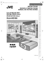
3.1 Cabinet Top, FN901 Removal
1. Remove 2 screws
A
(M3
×
8), 2 screws
B
(M3
×
6) and
pull the Cabinet Top upward off.
2. Remove 2 screws
C
(M2.5
×
6), disconnect terminal
“K6J” on the Main Board and then pull the fan duct
ass’y upward off.
3. Remove 2 screws
D
(T3
×
6) and remove fan “FN901”.
Part 2: Repair Information
2-5
The parts and screws should be placed exactly the same position as the
original otherwise it may cause loss of performance and product safety.
CAUTION
Screws Expression
(Type Diameter
×
Length) mm
T type
M Type
B
A
D
FN901
D
C
C
A
B
Cabinet Top
Fig. 2-5
Stopper Boss
Содержание LV-X4U
Страница 2: ...CANON Multimedia Projector LV X4U D78 5532 LV X4E D78 5533 SERVICE SMANUAL ...
Страница 9: ...Part 1 General Information ...
Страница 26: ...Part 2 Repair Information ...
Страница 43: ...Part 3 Adjustment ...
Страница 62: ...Part 4 Troubleshooting ...
Страница 79: ...Part 4 Troubleshooting 4 17 AN5870SB RGB SYNC SW IC5201 LM4889 Audio Amplifier IC5031 ...
Страница 81: ...Part 4 Troubleshooting 4 19 FA5502 P F Control IC621 VPC3230D Video Decoder IC101 ...
Страница 82: ...Part 4 Troubleshooting 4 20 L3E07070 Signal Processor for TFT LCD IC401 NJW1141 Audio Selector IC5001 ...
Страница 83: ...Part 4 Troubleshooting 4 21 STR Z2156A Power Switching Control IC631 PW168A Scaler Main CPU IC301 ...
Страница 84: ...Part 4 Troubleshooting 4 22 TA1370FG Sync Separator Frequency Counter IC5302 ...
Страница 85: ...Part 5 Parts Catalog ...
Страница 86: ......
Страница 94: ......
Страница 96: ...V 1 U 2 U 1 V 2 Z 1 Z 2 X Y W Accessories Page 5 CANON LV X4J LV X4U LV X4E REF NO D78 5531 D78 5532 D78 5533 ...
Страница 100: ...Part 6 Electrical Diagrams ...