Chapter 6
6-4
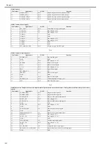
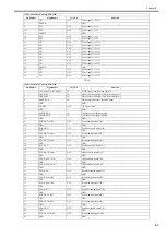
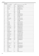
T-6-10
T-6-11
T-6-12
T-6-13
2
GND
-
GND
3
SUPPLY_BEN_R_SNS*
IN
Ink supply valve open/closed detection sensor (R) output signal
4
SNS3V_FU1
OUT
Power supply (+3.3V)
5
GND
-
GND
6
TAIKI_BEN_R_SNS*
OUT
Air passage valve open/closed detection sensor (R) output signal
7
INKBEN_R_OUTB
OUT
Valve motor (R) drive signal B
8
INKBEN_R_OUTA
OUT
Valve motor (R) drive signal A
9
TANK_DAT3
IN/OUT
Ink tank data signal 3
10
TANK_DAT4
IN/OUT
Ink tank data signal 4
11
TANK_3V
OUT
Power supply (+3.3V)
12
TANK_DAT5
IN/OUT
Ink tank data signal 5
13
GND
-
GND
14
TANK_CLK
OUT
Ink tank clock signal
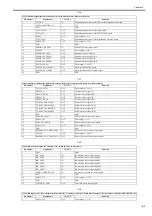
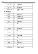
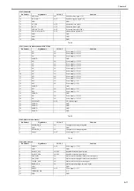
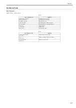
J3301 (Ink detection sensor (L), Ink tank cover switch (L))
Pin Number
Signal name
IN/OUT
Function
1
GND
-
GND
2
INK_SNS0
IN
Ink detection sensor output signal 0
3
INK_SNS1
IN
Ink detection sensor output signal 1
4
INK_SNS2
IN
Ink detection sensor output signal 2
5
INK_SNS6
IN
Ink detection sensor output signal 6
6
INK_SNS7
IN
Ink detection sensor output signal 7
7
INK_SNS8
IN
Ink detection sensor output signal 8
8
TANK_COVER_SW_L*
IN
Ink tank cover switch (L) output signal
9
GND
-
GND
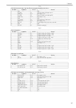
J3302 (Ink supply valve open/closed detection sensor (L), Air passage valve open/closed detection sensor (L), Valve motor (L), Ink tank ROM PCB (L))
Pin Number
Signal name
IN/OUT
Function
1
SNS3V_FU1
OUT
Power supply (+3.3V)
2
GND
-
GND
3
SUPPLY_BEN_L_SNS*
IN
Ink supply valve open/closed detection sensor (L) output signal
4
SNS3V_FU1
OUT
Power supply (+3.3V)
5
GND
-
GND
6
TAIKI_BEN_L_SNS*
OUT
Air passage valve open/closed detection sensor (L) output signal
7
INKBEN_L_OUTB
OUT
Valve motor (L) drive signal B
8
INKBEN_L_OUTA
OUT
Valve motor (L) drive signal A
9
TANK_DAT3
IN/OUT
Ink tank data signal 3
10
TANK_DAT4
IN/OUT
Ink tank data signal 4
11
TANK_3V
OUT
Power supply (+3.3V)
12
TANK_DAT5
IN/OUT
Ink tank data signal 5
13
GND
-
GND
14
TANK_CLK
OUT
Ink tank clock signal
15
N.C.
-
N.C
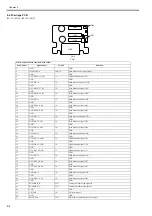
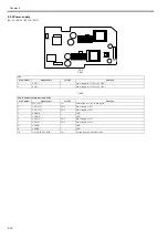
J3303 (Connect to Maintenance cartridge relay PCB)
Pin Number
Signal name
IN/OUT
Function
1
MENT_ROM_SDA
IN/OUT
Maintenance cartridge rom control signal (data)
2
MENT_ROM_SCL
IN/OUT
Maintenance cartridge rom control signal (clock)
3
GND
-
GND
4
TANK_3V
OUT
Power supply (+3.3V)
J3401 (Connect to Carriage PCB J201)
Pin Number
Signal name
IN/OUT
Function
1
VHGND
-
GND
2
VHGND
-
GND
3
VHGND
-
GND
4
VHGND
-
GND
5
VH_MONI1
IN
VH control signal
6
VH
OUT
Power supply (+21.5V)
J3202 (Ink supply valve open/closed detection sensor (R), Air passage valve open/closed detection sensor (R), valve motor (R), Ink tank ROM PCB (R))
Pin Number
Signal name
IN/OUT
Function
Содержание iPF750 series
Страница 1: ...Jul 25 2012 Service Manual iPF760 750 series ...
Страница 2: ......
Страница 6: ......
Страница 11: ...Chapter 1 PRODUCT DESCRIPTION ...
Страница 12: ......
Страница 14: ...Contents 1 7 3 5 Self diagnostic Feature 1 71 1 7 3 6 Disposing of the Lithium Battery 1 72 ...
Страница 87: ...Chapter 2 TECHNICAL REFERENCE ...
Страница 88: ......
Страница 99: ...Chapter 2 2 9 ...
Страница 145: ...Chapter 3 INSTALLATION ...
Страница 146: ......
Страница 148: ......
Страница 152: ......
Страница 153: ...Chapter 4 DISASSEMBLY REASSEMBLY ...
Страница 154: ......
Страница 156: ......
Страница 214: ...Chapter 4 4 58 2 Shaft Cleaner 1 F 4 119 1 ...
Страница 215: ...Chapter 4 4 59 3 Upper Cover Hinge Catch 1 Roll Cover Slide Guide 2 F 4 120 2 1 ...
Страница 218: ......
Страница 219: ...Chapter 5 MAINTENANCE ...
Страница 220: ......
Страница 222: ......
Страница 227: ...Chapter 5 5 5 ...
Страница 228: ......
Страница 229: ...Chapter 6 TROUBLESHOOTING ...
Страница 230: ......
Страница 232: ......
Страница 250: ......
Страница 251: ...Chapter 7 SERVICE MODE ...
Страница 252: ......
Страница 254: ......
Страница 305: ......
Страница 306: ......
Страница 307: ...Chapter 8 ERROR CODE ...
Страница 308: ......
Страница 310: ......
Страница 327: ...Jul 25 2012 ...
Страница 328: ......


