COPYRIGHT © 1998 CANON INC. FINISHER-C1/SADDLE FINISHER-C2 REV. 0 DEC. 1998 PRINTED IN JAPAN (IMPRIME AU JAPON)
3-6
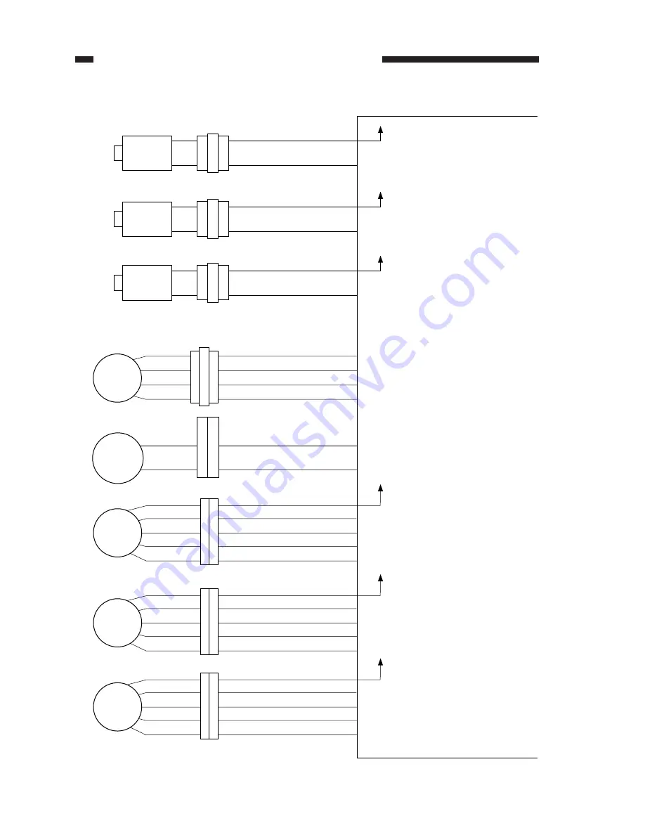
CHAPTER 3 SADDLE STITCHER UNIT BASIC OPERATION
4.
Outputs from the Saddle Stitcher Controller PCB
No. 1 paper deflecting solenoid
J15-1
-2
-1
-2
-1
-2
+24V
FLPSL1*
SL1S
J118
Saddle stitcher controller PCB
No. 2 paper deflecting solenoid
J15-3
-4
-1
-2
-1
-2
+24V
SL2S
J117
Feeding roller solenoid
J15-5
-6
-1
-2
-1
-2
+24V
RLNIPSL*
SL4S
J116
FLPSL2*
J5-1
-2
-3
-4
A
A*
B
B*
M1S
Feeder motor
J4-8
Paper folder motor
M2S
-7
-2
-1
Guide motor
B*
A*
B
A
M3S
J112-3
J119-5
-4
-3
-2
-1
J12-1
-2
-3
-4
-5
+24V
Paper positioning plate motor
A*
B
A
M4S
J114-5
-4
-3
-2
-1
J7-6
-7
-8
-9
-10
+24V
B*
Alignment motor
A*
B
A
M5S
J113-5
-4
-3
-2
-1
J7-1
-2
-3
-4
-5
+24V
B*
J115A
J115-1
-2
-3
-4
J115-4
-3
-2
-1
The states (+ and -) change
according to the rotation of the motor.
The pulse signals change
according to the rotation of the
motor.
The pulse signals change
according to the rotation of the
motor.
The pulse signals change
according to the rotation of
the motor.
The pulse signals change
according to the rotation of
the motor.
When '0', the solenoid
turns ON.
When '0', the solenoid
turns ON.
When '0', the solenoid
turns ON.
Figure 3-106


