background image

3 System Connections 


Unpacking the Supplied Equipment 


17 


Unpacking the Supplied Equipment 

Grab the camera head by the handle, remove it from the package and place 
it on a stable work surface. 


To transport the camera head after use, carefully pack it in the 
same position it was shipped.


Removing the Units Originally Attached to the Camera Head   

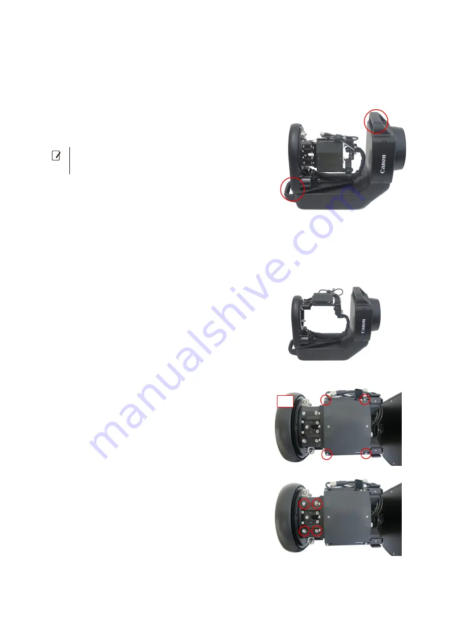
This product is shipped with the camera mounting bracket and IP controller originally attached to the camera head. To 
begin the connection process, first remove these units. 

1.


Turn the camera rotator clockwise so the IP controller is on 
top.   


2.


Loosen the hex head bolts at the corners of the IP controller 
(M3, x4).   


3.


Loosen the camera mounting bracket’s hex head bolts   
(M5, x4).   

4.


Turn the camera rotator 180 degrees counter-clockwise.   


Top 

Содержание CR-S700R

Страница 1: ...5 000A CR S700R Robotic Camera System Instruction Manual Before using the product carefully read this Instruction Manual and be sure to use the product correctly Retain the Instruction Manual for future reference ...

Страница 2: ...Plate optional 14 3 System Connections 15 Preparations 15 Things to Check before Connecting the System 15 Overview of the Installation Process 16 Unpacking the Supplied Equipment 17 Removing the Units Originally Attached to the Camera Head 17 Preparing the Camera Unit 19 Attaching a Lens to the Main Capture Camera and Inserting the Recording Media 19 Setting Up the Main Capture Camera and Lens 19 ...

Страница 3: ...ing the Camera Head 35 Connecting the Main Capture Camera 35 Connecting the Wide View Camera and Eyepiece Camera 35 Organizing Tidying Up the Cables 35 Standing Up the Camera Head 36 Connecting a Power Source and Network 36 Turning the System On Off 37 Checking the System 38 Attaching the Optional Rain Cover 39 Attaching the Front Cover 39 Attaching the Rear Cover 39 Attaching the Optional Base Pl...

Страница 4: ...x 49 Torque Value Guidelines for Tightening Bolts 49 Gear Ring Attachment Positions 49 Connection Installation Checklist 50 Detailed Dimensions 52 CR S700R Robotic Camera Head 52 CR BP100 Base Plate 53 7 Index 54 ...

Страница 5: ...tening the necessary screws according to the instruction manual If the product is not firmly secured or if screws are loose the product may topple over or fall down resulting in injury and accidents When installing the product in an elevated location make sure to take appropriate measures in advance to prevent the equipment and parts from falling off Equipment falling down may cause serious injury...

Страница 6: ...posed to salt water or where corrosive gases or oily smoke are present Contact with such substances may corrode and degrade the mountings causing the product to fall down and cause injury When transporting the robotic camera head always use two people to lift it firmly grabbing the handles Dropping the product may damage it and cause injury and accidents Handling Make sure there are no people with...

Страница 7: ...at results from using the product for the customer s purpose 3 Canon shall make no guarantees about the results obtained using this product 4 The product specifications configuration and appearance are subject to change without prior notice 5 For further information on repairs maintenance or adjustments not mentioned in this instruction manual contact a Canon sales representative 6 Note that Canon...

Страница 8: ... CR G100 IP Camera Controller Camera Mounting Bracket Lens Supporter for EF70 200mm Lens Supporter for EF100 400mm Zoom Unit Zoom Unit Shafts A B Wide View Camera Bracket Eyepiece Camera Bracket and USB Cable N3 Cable LAN Cable USB Cable type C for EOS 1D X Mark II USB Cable type C for EOS 1D X Mark III DC Coupler Ferrite Cores x2 Comes pre attached to the CR S700R ...

Страница 9: ...controller to operate the system and check a streamed image with a very small lag while recording For details about using the software refer to the Camera Remote Application Operation Guide Make sure to always use the latest IP controller s firmware version and Camera Remote application s software version Commercially Available Accessories Tested with this System As wide view camera Watec s WAT 02...

Страница 10: ...Configuring network settings requires adequate knowledge about configuring and using wired Ethernet networks Canon cannot provide support regarding network configurations Conventions Used in this Document Information and precautions that is important you follow Additional information you should know A Reference page number Camera head refers to the CR S700R Robotic Camera Head unit IP controller r...

Страница 11: ...tely CR S700R Robotic Camera Head CR G100 IP Camera Controller Camera Remote Application CR A100 sold separately FTP server commercially available Web setup tool CR G100 Ethernet USB N3 Power supply Eyepiece camera commercially available Wide view camera commercially available ...

Страница 12: ...ogo plate The plate can be installed upside down if necessary 6 Base unit 7 Cable assembly A 25 8 Cable clamp A 17 27 9 Fastener A 35 39 10 Power switch A 37 11 STATUS indicator A 37 12 ALARM indicator A 47 Illuminates if the system reaches a critical condition 13 DC IN 24V terminal A 36 14 LAN Ethernet terminal A 36 1 2 3 2 5 6 4 7 8 9 10 12 13 14 11 ...

Страница 13: ...Power cable A 34 4 LAN cable A 34 5 Head interface cable A 34 6 Screw holes for M8 fixation bolts 12 mm 0 47 in deep x4 URC S1 Camera Remote Rain Cover optional 1 Front cover A 39 2 Rear cover A 39 3 Front cover extender for 100 400mm lenses A 39 4 Front cover ring A 23 6 1 3 2 4 5 ...

Страница 14: ...oles for safety eye bolt x4 2 Screw holes for camera head fixation screws x4 3 Screw holes for V type attachment mount 3 8 x9 M5 x10 4 Screw holes for 50 mm 2 0 in clamp 10 mm 0 39 in x6 5 Screw holes for 50 mm or 60 mm 2 0 in or 2 4 in clamp 12 mm 0 47 in x6 1 1 2 2 3 4 4 5 5 ...

Страница 15: ...II USM B long Front cover EF24 70mm F2 8L II USM EF24 105mm F4L IS II EF70 200mm F2 8L IS II USM For EF70 200mm lenses EF100 400mm F4 5 5 6L IS II USM For EF100 400mm lenses Rotator s subject side Front cover extender for 100 400mm lenses When using the EF11 24mm F4L USM lens vignetting may appear at full wide angle If the noise of the camera mounting bracket s bolts is a nuisance you can use the ...

Страница 16: ...and cable clamp from the camera head 3 Prepare the camera unit and set up the main capture camera and lens Camera unit refers collectively to the main capture camera with a lens and camera mounting bracket attached 4 If using a rain cover attach the front ring 5 Attach the zoom unit to the camera head but tighten it only partially 6 Mount the camera unit on the camera head 7 Attach the gear ring t...

Страница 17: ...Removing the Units Originally Attached to the Camera Head This product is shipped with the camera mounting bracket and IP controller originally attached to the camera head To begin the connection process first remove these units 1 Turn the camera rotator clockwise so the IP controller is on top 2 Loosen the hex head bolts at the corners of the IP controller M3 x4 3 Loosen the camera mounting brack...

Страница 18: ... and slide it in the direction of the arrow to remove it 6 Loosen the fastener and release the cables that were tied together 7 Loosen the cable clamp s hex head bolts M5 x2 and remove the cable clamp 8 Slide the camera mounting bracket in the direction of the arrow to remove it Final situation after the procedure Top ...

Страница 19: ... Up the Main Capture Camera and Lens For details about changing the settings on the main capture camera and lens refer to their respective instruction manuals 1 Set the lens s focus mode AF MF switch to AF 2 Set the lens s image stabilizer STABILIZER switch to OFF 3 Turn on the main capture camera 4 On the main capture camera select the AF mode and drive mode according to the shooting conditions 5...

Страница 20: ...main capture camera Attaching a Lens Supporter to the Lens When using an EF70 200mm or EF100 400mm lens attach the corresponding lens supporter to the lens using an hex head bolt M5 Adjusting the Camera Mounting Bracket s Positioning Element The positioning element on the camera mounting bracket is only necessary when using a lens that does not require a lens supporter When using one of the lenses...

Страница 21: ...of the main capture camera Align the camera supporting bracket s hex head bolt 1 4 with the camera s tripod socket and screw it in only partially using the 4 mm hex wrench 3 Lenses with a tripod mount Loosen the orientation locking knob 4 Align the camera mounting bracket s hex head bolts M5 x3 with the screw holes on the camera mounting bracket and screw them in only partially If necessary slide ...

Страница 22: ...sary align the camera supporting bracket s hex head bolt 1 4 with the camera s tripod socket and screw it in only partially using the 4 mm hex wrench 2 Move the tripod socket s bolt along the rail so the camera is aligned perfectly straight with the camera mounting bracket 3 Fasten the hex head bolt firmly to secure it place Final situation after the procedure Bottom ...

Страница 23: ...t and secure the front ring in place using the hex head bolts M5 x4 Attaching the Zoom Unit The type of shaft required and the position in which the zoom unit is attached depend on the lens used A 15 Attaching the Zoom Unit Shaft Lenses Other than the EF100 400mm 1 Insert the zoom unit shaft B long from the side opposite the zoom unit s flat surface and secure it in place using an hex head bolt M5...

Страница 24: ...dless of the attachment position Lenses Other than the EF100 400mm Insert the zoom unit shaft into the camera rotator s shaft hole from the camera rotator s camera side EF100 400mm Lens Insert the zoom unit shaft into the camera rotator s notch from the subject side of the camera rotator 3 Attach an hex head bolt M6 so the zoom unit does not move inadvertently Use a 4 mm 0 16 in hex wrench to scre...

Страница 25: ...the top For underslung position 2 If the position does not match the mode in which you plan to use the system upright underslung replace the mounting for the camera mounting bracket Remove the fixation hex head bolts M5 x4 and attach the mounting for the camera mounting bracket to the opposite side When using the robotic camera system in underslung position for all the rest of the setup and instal...

Страница 26: ...mera head s cable assembly through the rain cover s rear cover Pass the cable assembly though the rear cover s smaller opening 3 Reattach the part you removed in step 1 to the cable clamp and secure it using hex head bolts M5 x2 Final situation after the procedure ...

Страница 27: ...amera mounting bracket all the way into the camera rotator s mounting 3 Attach the cable clamp to the back of the camera mounting bracket and secure it in place using hex head bolts M5 x2 4 Turn the camera rotator 180 degrees clockwise so the bottom of the camera is on top 5 Secure the camera unit in place using hex head bolts M5 x4 Final situation after the procedure Slide up the guides on both s...

Страница 28: ... without any slack and with the screw side facing up If the extra part at the end of the gear ring is too long it may obstruct the operation of moving parts In such case cutting the end of the gear ring leaving only 1 2 cm 0 39 0 79 in is recommended Fixing the Zoom Unit 1 Turn the camera rotator clockwise so the zoom unit is on top 2 Holding the zoom unit in place loosen the fixation hex head bol...

Страница 29: ... the camera rotator to connect it Place the cable in such a way that it does not obstruct the operation of the zoom unit s gear and gear ring 5 Lenses other than the EF100 400mm Bundle the safety wire that you attached in step 3 with the zoom unit cable using a cable tie 6 Turn the lens s zoom ring until the wide angle end Final situation after the procedure If the lens is not initially set to the...

Страница 30: ... camera is on top 2 Place the IP controller on top of the camera mounting bracket and slide it in the direction of the arrow Secure it in place using hex head bolts M3 x4 Insert the tabs at the bottom of the IP controller into the corresponding ridges on the camera mounting bracket and slide it in Final situation after the procedure Top ...

Страница 31: ...erslung position attach the top of the wide view camera upside down 2 Attach the bracket to the camera rotator s side mounting and secure it in place using hex head bolts M5 x2 The hex head bolts can move so properly align them with the screw holes 3 Loop the wide view camera s USB cable about 3 times and tuck it inside the bracket as shown in the picture Use a cable tie or other means to hold the...

Страница 32: ... subject distance approx 10 m 32 8 ft If the focus shifts easily use adhesive tape around the lens as shown in the illustration to physically secure it in place 3 Turn the camera rotator counter clockwise so the main capture camera is on top 4 Attach the eyepiece camera to the eyepiece camera bracket and secure it in place using hex head bolts M2 x2 5 Remove the lens cap from the eyepiece camera 6...

Страница 33: ...piece camera Pass the cable through the bracket s cable removal prevention fitting and secure the bracket in place using hex head bolts on both sides of the rear part M3 x2 Final situation after the procedure After attaching configuring and adjusting the eyepiece camera you can use the Windows default Camera app or other software to check the image ...

Страница 34: ...ore connecting the cables make sure to turn off the camera head Ethernet hub FTP server DC coupler 5 LAN cable supplied 4 USB Type C cable supplied CR S700R Robotic Camera Head 3 Power cable Zoom unit cable Main capture camera commercially available 1 Head interface cable 2 LAN cable CR G100 IP Camera Controller 6 N3 cable supplied 7 USB cable 8 USB cable Eyepiece camera commercially available Wid...

Страница 35: ...erminal and to the remote control terminal on the main capture camera 6 When connecting the N3 cable s right angle connector to the N3 Remote terminal make sure the connector and cable are oriented in the direction of the main capture camera Connecting the Wide View Camera and Eyepiece Camera When using a wide view camera and or eyepiece camera connect them to the IP controller For details about t...

Страница 36: ... for all network connections Power sources that can be used Connection Power supply specifications DC IN 24V terminal 3 pin XLR plug female connector 24 V to 28 V DC 8 A or higher acceptable maximum load current Connectors for outdoor water resistant installations Make sure to use the following connectors for the power and LAN cables Connector type Recommended connector Power connector NEUTRIK s N...

Страница 37: ... LAN Ethernet terminal to a port without power supply You can connect the control PC directly to the camera head s LAN Ethernet terminal without using an Ethernet hub In such case the control PC must be used also as the FTP server if you want to use the FTP transfer function Turning the System On Off Set the camera head s power switch to the top position to turn on the camera head The STATUS indic...

Страница 38: ...ns used after the first installation and whenever you replace the lens Pan tilt roll zoom operations and setting their motion range limits Checking images taken with the main capture camera Remote operation of the camera shooting settings shutter releasing and data transfers Physical position of switches on the camera and lens camera menu settings A 19 Switching to underslung mode if you plan to i...

Страница 39: ... If you had already set the camera head upright lay it down in the position just before connecting the cables as shown in the final situation picture on page 33 2 Attach the lens hood to the lens 3 Attach the front cover to the groove on the front ring that you installed on the camera rotator in advance Pull the string to tightly close the front cover s opening When using the EF100 400mm F4 5 5 6L...

Страница 40: ...the string to tightly close the cover s opening 3 Use the fastener to hold the end of the string in place 4 Adjust the other rear cover opening so it reaches the waterproof structure of the camera head s cable assembly Close the opening tightly with the 2 strings and use fasteners to hold the end of the strings in place Final situation after the procedure ...

Страница 41: ...a head and secure it in place using the hex head bolts M8 x4 supplied with the base plate Insert the bolts from the surface with the special bolt dents 2 If necessary attach the eye bolts M16 x4 3 If necessary attach the 50 mm 2 0 in clamps M10 x2 or the 50 mm 60 mm 2 0 in 2 4 in clamps M12 x2 When attaching eye bolts or clamps to the base plate use bolts that protrude at least as follows M10 11 m...

Страница 42: ... IP controller Disconnect the LAN cable from the main capture camera and IP controller Disconnect the USB cable from the main capture camera and IP controller Disconnect the camera head s LAN cable from the IP controller Disconnect the camera head s head interface cable from the IP controller Disconnect the camera head s power cable from the DC coupler of the main capture camera Disconnect the zoo...

Страница 43: ...osition turn the camera mounting bracket so it is at the bottom and remove the lens supporter or positioning element 4 Turn the bracket so the bottom of the camera is facing up 5 Slide the camera mounting bracket toward the lens move the camera so the tripod socket s hex head bolt is at the end of the screw hole s rail and then loosen the hex head bolt completely and remove the camera 6 If a lens ...

Страница 44: ...it does not fall or topple Use safety wires and other measures as necessary When installing the camera head outdoors take all necessary precautions so it does not fall or is toppled over as a result of strong winds Always install the camera head in a location that is sufficiently sturdy and stable for the desired installation position upright underslung Installing the Camera Head Transportation In...

Страница 45: ...wires Wire attachment hole 5 mm 0 2 in Slits for cable tie bands 6 mm 0 24 in wide x2 Slits for cable tie bands 6 mm 0 24 in wide x2 Wire attachment hole 6 mm 0 24 in Wire attachment hole 14 mm 0 55 in Wire attachment hole 6 mm 0 24 in x2 Wire attachment hole 4 mm 0 16 in Wire attachment holes 10 mm 0 39 in wide x2 Slit for fastening strings 8 mm 0 31 in wide for the optional rain cover ...

Страница 46: ...anon logo on the base unit is aligned with the center of the camera head s pan motion range Even when using the base plate make sure to use clamps and bolts as necessary to firmly secure the system Testing the Operation Post Installation After installing the system at the shooting location verify again all the points described in Checking the System A 38 in the previous chapter Removing the Camera...

Страница 47: ...he AC adapter is properly connected A 36 The camera head is not responding Check the connection status of all the devices in the Status screen of the web setup tool If the camera head is not recognized check the connections between the camera head and IP controller A 35 The camera head is not turning in the correct direction In the web setup tool Underslung mode is not activated The system emits a...

Страница 48: ...d 1 sec to 90 sec Fixtures Attachment using M8 hex head bolts x4 DC IN 24V terminal XLR 3 pin connector Nominal input 24 V to 28 V DC approx 160 W Recommended power supply 200 W or higher output Recommended power cable allowable current capacity 8 A or higher resistance below 0 25 Ω LAN terminal Ethernet 1000BASE T compatible RJ45 connector Maximum power consumption Approx 160 W Dimensions W x H x...

Страница 49: ...strations as a reference when attaching the gear ring to the lens Lens Type Recommended position Tolerance EF11 24mm F4L USM A 6 0 mm 0 24 in 5 7 to 6 0 mm EF16 35mm F2 8L III USM A 6 0 mm 0 24 in 5 0 to 9 0 mm EF24 70mm F2 8L II USM A 6 0 mm 0 24 in 5 0 to 10 0 mm EF24 105mm F4L IS II USM A 6 0 mm 0 24 in 5 0 to 10 0 mm EF70 200mm F2 8L IS II USM A 3 5 mm 0 14 in 0 to 4 5 mm EF100 400mm F4 5 5 6L...

Страница 50: ...tions and its focus is correctly adjusted The lens s zoom position is set to the wide angle end before turning on the camera head All the necessary safety drop prevention measures are installed The rain cover openings are closed tightly water leak prevention The camera head is securely mounted on a stable location The camera head is correctly connected to a network and power supply at the shooting...

Страница 51: ...sharp and clear If not correct as necessary performing the dioptric adjustment on the main capture camera All the operations can be correctly controlled with the Camera Remote application The images recorded on the main capture camera s card can be correctly acquired Images are correctly transferred to the FTP server Web setup tool Final homing procedure was performed before turning off the system...

Страница 52: ... 52 Detailed Dimensions CR S700R Robotic Camera Head 411 382 522 8 90 10 5 235 2 260 optical axis center 260 pan axis center 192 136 390 optical axis center 390 tilt axis center 145 2 tilt axis center 145 2 pan axis center 4x M8 12 ...

Страница 53: ...CR BP100 Base Plate 90 8 5 130 179 230 A A 400 349 200 136 128 SECTION A A DETAIL C SCALE 1 2 DETAIL B SCALE 1 2 2 2 1 1 14 8x25 4 203 2 8x25 4 63 63 63 55 63 25 40 60 10xM5 9xCU3 8 16 ø 18 ø 13 ø 9 ø 3 ø 42 15 4 6 8 30 10 11 13 10 2 1 ...

Страница 54: ...Connected devices 38 Connections 15 35 DC coupler 19 35 DC IN 24V terminal 12 36 48 Detailed dimensions 52 Disclaimers 7 Eye bolt commercially available 14 41 Eyepiece camera 9 32 35 Eyepiece camera bracket 32 EYEPIECE CAMERA terminal 34 35 Front ring 23 FTP transfer 19 Gear ring 9 28 Handle 12 Handling precautions 6 Head interface cable 12 34 35 HEAD terminal 34 35 Homing 37 Installation 44 IP ca...

Страница 55: ...tools and equipment 15 16 Robotic camera head 12 48 Rotation range 48 Safety drop prevention measures 44 Safety eye bolts 14 41 Safety instructions 5 Safety wire 12 44 Screw holes for fixation bolts 13 Specifications 48 STATUS indicator 12 37 System chart 11 Testing the operation of the main capture camera 38 Tripod socket 21 Troubleshooting 47 Turning the system on off 37 Underslung position 15 2...

Страница 56: ... CANON INC 2020 Canon Inc 30 2 Shimomaruko 3 chome Ohta ku Tokyo 146 8501 Japan The information in this document is verified as of January 2020 Subject to change without notice ...

Отзывы: