background image

EdgeAccess 


Chapter 5 

Specifications and Pinouts 

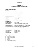
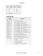
3240S Specifications 

Electrical 


Power: 

115 AC ±10% @ 0.5 amp 


230 VAC @ 0.25 amp (optional) 


47 to 63 Hz (both) 


-48 VDC (optional) 

Dimensions/Environmental 


Stand alone: 

3.5" H x 17" W x 13.5" D 

Weight: 

11 lbs. (3.6 Kg) 

Temperature: 

0 to 50°C 

Humidity: 

0 to 95% (non-condensing) 

Optical Interface 


Composite Error Rate: 

1 in 10

9

 or better 

Fiber Compatibility: 

50 to 62.5 micron MM fiber (850 nm, 1310 nm) 
or 8 to 10 micron SM fiber (1310 nm, 1550 nm) 

Transmitter/Wavelength: 

Infrared LED or laser diode/850 nm, 1310 nm, 1550 nm 

LO/HI optical power switch: 

Reduces 850 nm Tx power by approximately 6 dB 
Reduces 1310 nm Tx power by approximately 3 dB 

Receiver: 


850 nm LED option: 

PIN diode standard 

1310 nm laser option: 

PIN (InGaAs) diode 

1550 nm laser: 

PIN (InGaAs) diode 

Transmission Code: 

Proprietary 


Regulatory Compliance 


UL 1950/CSA C22.2 No950 


FCC Part 15 Class A (pending) 


EN 60950 


IEC 60950 


EN 55022, EN 50081-1 (pending) 


3240S Fiber-Optic Multiplexer 

5-1


Содержание 3240S

Страница 1: ...Model 3240S SNMP Managed T1 E1 Fiber Optic Multiplexer User Manual...

Страница 2: ......

Страница 3: ...of its products at any time without prior notification Every effort has been made to keep the information in this document current and accurate as of the date of publication or revision However no gu...

Страница 4: ......

Страница 5: ...on d instruments optiques par exemple un collimateur optique avec cet quipement peut s av rer dangereuse pour les yeux Proc der des contr les des ajustements ou toute proc dure autre que celles d crit...

Страница 6: ......

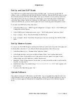
Страница 7: ...anagement Platform 3 1 Set Up the PC for Terminal Operation 3 1 Management User Interface 3 2 General Screen Format 3 2 User Interface Organization 3 3 Login and Main Menu 3 3 Manage the 3240S 3 4 Set...

Страница 8: ...ets 2 4 Figure 8 General Screen Format 3 2 Figure 9 Flowchart for Using Loopback in Troubleshooting 4 5 List of Tables Table 1 T1 Switch Settings for Line Length 2 2 Table 2 System LEDs 2 6 Table 3 Ma...

Страница 9: ...C power redundancy for both power and optics and 1300 1550 nm single mode and 850 1300 nm multimode fiber optics Figure 1 shows the front of the 3240S with the SNMP Management module Figure 2 shows th...

Страница 10: ...int application for either a managed or a non managed 3240S Figure 3 Typical Point to Point Application In a Master Slave Ring application one multiplexer is designated as the master it supplies the c...

Страница 11: ...o the network management module An optional HI LO power switch for each transmitter except low power transmitters provides compensation for link losses of typically more or less than 6 dB Use the 3240...

Страница 12: ......

Страница 13: ...only once In general set the card in physical slot 1 to time slots 1 and 3 set the card in physical slot 2 to time slots 2 and 4 To avoid confusion the management software flags an error if cards wit...

Страница 14: ...th Application SW1 or SW3 1 2 3 5 6 7 0 133 ft DSX 1 ABAM Wire AT T 600B 600C O O C O O C 133 266 ft DSX 1 ABAM Wire AT T 600B 600C C C O C C O 266 399 ft DSX 1 ABAM Wire AT T 600B 600C O C O O C O 39...

Страница 15: ...see Figure 6 and follow these steps 1 Set the time slot at jumper W3 Both ends of each link must be set to the same time slot Install the jumper for time slots 1 and 3 Remove the jumper for time slots...

Страница 16: ...the thumbscrews and grasp them to pull the card out Normally installed at the factory you can install the SNMP module in the field see Figure 1 Caution The SNMP module is not hot swappable 4 Remove t...

Страница 17: ...then if a transmitter is a high power laser set the HI LO Optical Power switch In general set the switch to LO for a link loss of less than 6 dB or to HI for a link loss of more than 6 dB Front and R...

Страница 18: ...power supply s SYNC LOSS Off Normal operation On Optical receiver cannot synchronize with the signal coming from the remote multiplexer LOOP Off Normal operation On Loopback active follows MODE switc...

Страница 19: ...t to point application set the MAST SLV switches on both multiplexers to MAST For a master slave ring application set the Master Slave switch on one unit to MAST and all others to SLV If included set...

Страница 20: ...EdgeAccess 2 8 3240S Fiber Optic Multiplexer...

Страница 21: ...sion directly to the 3240S Setting up the VT100 session depends on which connection serial port or Ethernet you have available for access to the VT100 management program Canoga Perkins suggests that y...

Страница 22: ...n Format Not all screens and menus provide options that you can change Some menu items reach screens that only report status such as revision numbers module type or alarms On other screens you can mov...

Страница 23: ...ostics 4 Software Upgrade 5 Modem Setup Login and Main Menu The first screen is the Login Menu If this is your initial setup and no password has been set press Enter at the prompt for the password Oth...

Страница 24: ...eps at the SNMP Agent Configuration screen 1 At the Main Menu type 1 SNMP Agent Configuration and press Enter The SNMP Agent Configuration screen appears 2 Type the number for an item and press Enter...

Страница 25: ...prompts on the screen to manage the 3240S in SLIP mode Set Up Modem Access You can access the 3240S through a modem which allows an extra level of security with a password for the modem connection To...

Страница 26: ...ter the upgrade starts automatically Manage Security To provide system security the 3240S includes username and password access as well as SNMP with Read and Write communities and a Host table The SNM...

Страница 27: ...especially those who are not logged in To update your password follow these steps 1 From the Main menu type 6 User Interface Password and press Enter 2 To change your password follow the prompts on th...

Страница 28: ...ow the prompts to enter the unit and port numbers and select your Line Coding Note To enable software control set the switches and jumpers on the board for T1 see page 2 1 or for E1 see page 2 3 5 To...

Страница 29: ...t jumpers are mismatched see page 2 1 7 Card Insert Remove An I O card is inserted or removed 8 Backup Link OK Bad The backup link changes between good and failed 9 Cold Start Authentication The 3240S...

Страница 30: ......

Страница 31: ......

Страница 32: ......

Страница 33: ...e typical long term low stress radius is not less than 15 times the cable diameter based on Federal Standard FS 1037C Always connect the fiber optic cables in the standard Tx to Rx and Rx to Tx scheme...

Страница 34: ...ract that value from the 3240S Tx output value to determine the power expected at the remote cable end which is the input power at the remote receiver and skip this section Otherwise continue these st...

Страница 35: ...tings on the interface and back panel on the local and the remote 3240S If the jumper and switch settings are correct and the data still fails to pass composite loopback replace the cable If the data...

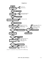
Страница 36: ...loopback returns the received electrical signal to the local site and ignores the received optical signal Faulty data can indicate that the local 3240S is faulty Remote I O port loopback sends the si...

Страница 37: ...ower value Replace remote mux Replace local Rx fiber Values for lowest received power 850 nm 33 db 1310 nm HI pwr 1550 nm 32 dB 1310 nm LO pwr 24 dB Values for lowest transmitted power 850 nm 21 5 4 d...

Страница 38: ...pe 1 and press Enter 6 To return to the Main Menu press Esc To run composite loopback manually follow these steps 1 At the rear panel set the System Mode switch to LOC for local loopback or to REM for...

Страница 39: ...to 62 5 micron MM fiber 850 nm 1310 nm or 8 to 10 micron SM fiber 1310 nm 1550 nm Transmitter Wavelength Infrared LED or laser diode 850 nm 1310 nm 1550 nm LO HI optical power switch Reduces 850 nm T...

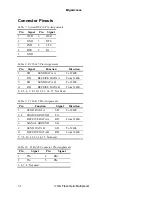
Страница 40: ...D DATA B To 3240S 11 RD RECEIVE DATA B From 3240S 2 4 5 6 7 8 10 12 13 14 15 Not Used Table 9 T1 DA 15 Pin Assignments Pin Function Signal Direction 1 SEND DATA A SD To 3240S 2 4 FRAME GROUND FG 3 REC...

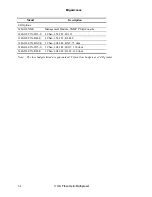
Страница 41: ...FC PC 3240 BU 37 x S 1310 nm SM MM 13 dB Redundant Laser FC PC 3240 BU 11 x S 1310 nm SM MM 23 dB Laser ST 3240 BU 31 x S 1310 nm SM MM 23 dB Redundant Laser ST 3240 BU 13 x S 1310 nm SM MM 23 dB Las...

Страница 42: ...n 1 544 T1 DA 15 3240 IO T1X R48 S 4 Chan 1 544 T1 RJ 48C 3240 IO E1X BNC S 3 Chan 2 048 E1 BNC 75 ohm 3240 IO E1X D15 S 3 Chan 2 048 E1 DA15 120 ohm 3240 IO E1X R48 S 3 Chan 2 048 E1 RJ 45 120 ohm No...

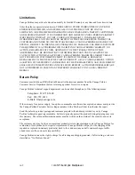
Страница 43: ...chanical components or alteration or repair by anyone other than Canoga Perkins or its authorized representative If the user is unsure about the proper means of installing or using the equipment conta...

Страница 44: ...RE NOT AUTHORIZED TO EXTEND ANY DIFFERENT WARRANTY ON CANOGA PERKINS BEHALF Return Policy Customer must obtain an RMA Return Material Authorization number from the Canoga Perkins Customer Service Depa...

Страница 45: ...ysical slots 2 1 PING 4 4 point to point application 1 2 R redundancy optic 1 3 3 7 4 3 power 1 3 S screen Host Access screen 3 6 Main Menu 3 3 PING Generation 4 4 SNMP Configuration 3 4 3 5 Software...

Страница 46: ......

Страница 47: ......

Страница 48: ......

Страница 49: ......

Страница 50: ...CANOGA PERKINS CORPORATION 20600 Prairie Street Chatsworth California 91311 6008 USA Phone 818 718 6300 FAX 818 718 6312 Web Site www canoga com Email fiber canoga com...

Отзывы: