18
GAS CONTROL
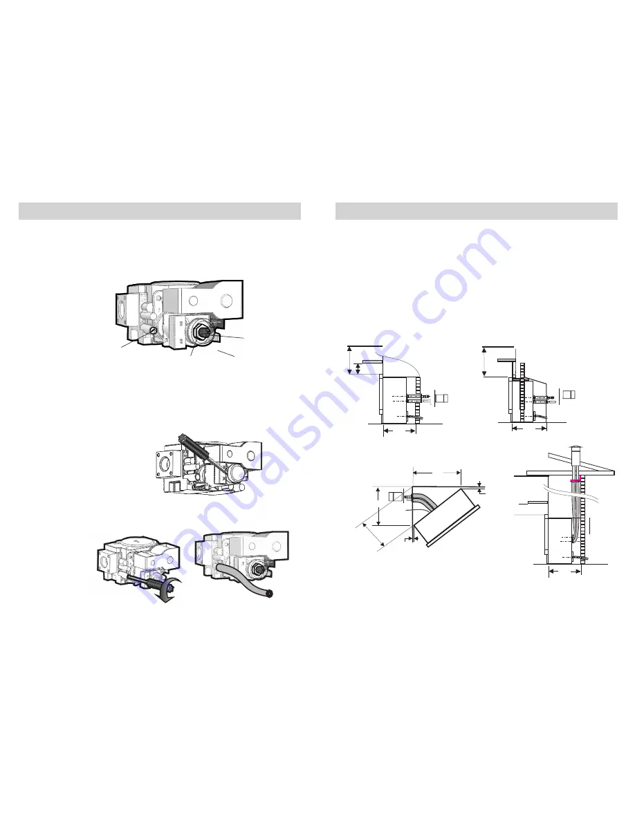
23. Gas control layout is as indicated in figure 23.
Pressures for ‘Burner full on’ and ‘Burner low flame’ are factory
set, however if pressures need to be checked or adjusted follow the
procedures described below and on the next two pages.
To check control outlet pressure at burner ‘Full on” and ‘Low Flame”
positions remove the plastic cap from the regulator adjustment location
as indicated in figures 24 .
Gas pressure point
24. The pressure point is closed with a captive screw. Turn screw 6 revo-
lutions anticlockwise to open the pressure point as indicated on figure
25 (a) and place manometer tube over the test point as per figure 25(b).
Important: To
achieve the correct
visual flame effect:
On Propane the gas
pressure must be set
at 2.65 kPa with
burner operating on
maximum setting.
On Natural Gas the
gas pressure must
be set at 0.75 kPa
with burner operat-
ing pressure on
maximum setting.
Plastic Cap
Pressure adjustment
(Burner ‘Full on’)
Burner adjustment
(Burner ‘Low flame’)
Pressure test point
with captive screw
485 min
300
1000 MIN
TO CEILING
485 min
TO CEILING
1000 MIN
MASONARY
FIREPLACE
APPLICATION
THROUGH WALL
APPLICATION
TIMBER or BRICK
*1*
*1*
*2*
*2*
CONSULT
MOCK FIRE
INSTRUCTION BOOKLET
REQUIREMENTS
FOR THIS APPLICATION
FLUEING OPTIONS
517
517
25
min
383
CORNER WALL
APPLICATION
*1*
*2*
CONSULT
MOCK FIRE
INSTRUCTION BOOKLET
REQUIREMENTS
FOR THIS APPLICATION
25min
*1* For any horizontal application top hat section can be removed.
*2* Condensation drain must have sufficient fall to provide adequate drainage.
ensure no water traps occur in drain.
585 min
Vertical flue installation -
using extended flue kit code
FLUEWFX
* 2*
11
FIG 8.
FIG 25a.
FIG 24.
FIG 23.
FIG 25b.
The heater is supplied with components to suit a horizontal flue coming
through a wall at the back of the heater. The Components include a flue cowl
which is designed to be fitted to the outside wall with suitable fasteners.
Condensate drain tube 2m and Clamp, and flexible tube sealant.
Flexible ducting is provided to attach the heater to the flue cowl. The use of
this ducting provides for some flexibility in the manner the flue and intake air
are connected.The flue and air intake components are fully attached to the
heater prior to the heater being fitted into the cavity.
When flueing the through the roof the Extended Flue Kit is required code
FLUEWFX. The maximum length of flue pipes that can be used with the
Powerflue heater is 6.0m.
The Cannon appliance is warranted against defects in materials and
Warranty service, which includes parts and labour for the replacement or
repair of defective parts, is available through the CANNON distributor.
(Details below or on page 24).
Consumers are responsible for service person’s travel outside normal
service areas (approximately seventy (70) kilometer radius from the nearest
Cannon dealer’s location), local transport costs, or any preventative
maintenance works as described in
Any product subjected to misuse, abuse, negligence, accident or alteration
will have its warranty voided. The defacement of serial plate will also void
warranty.
If installation is not carried out in accordance with manufacturer’s
instructions, this warranty may be void.
The customer must keep their “Tax Invoice” as proof of purchase of this
product and compliance certificate as proof of required installation.
workmanship for a period of two (2) years from its date of original
purchase, applicable only for residential use in Australia.
this manual.
Enter the details of the date installed and the Compliance Certificate
number in the appropriate area on the rear page of this manual.


