background image

26

26

PAINTED PARTS AND SILKSCREEN PRINTED SURFACES

Clean using an appropriate product. Always dry thoroughly.

IMPORTANT:

 these parts must be cleaned very carefully to avoid scratching and abrasion.

You are advised to use a soft cloth and neutral soap.

CAUTION: Do not use abrasive substances or non-neutral detergents as these will 

irreparably damage the surface.

Note: Continuous use may cause a change in the glaze around the burners, 

corresponding to the areas exposed to the heat.

GAS TAPS

Do not let cleaning products come into contact with the valves.

Periodic lubrication of the gas taps must be carried out by specialist personnel only.

In the event of operating faults in the gas taps, call the Service Department.

BURNERS AND PAN SUPPORTS

These parts must be cleaned using a sponge and soapy water or other suitable non-

abrasive products. Dry with a soft cloth.

Warning! Not dishwasher safe.

After  cleaning,  the  burners  and  their  flame  spreaders  must  be  well  dried  and  correctly 

replaced.

It is very important to check that the burner flame spreader and the cap have been correctly 

positioned. Failure to do so can cause serious problems.

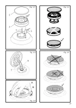
Check that the electrode “

S

”  (figs.  3.1,  3.3)  next  to  each  burner  is/are  always  clean  to 

ensure trouble-free sparking.

Check that the probe “

T

” (figs. 3.1, 3.3) next to each burner is/are always clean to ensure 

correct operation of the safety valves.

Both the probe and ignition plug must be very carefully cleaned.

Note: To avoid damage to the electric ignition do not use it when the burners are not 

in place.

CORRECT REPLACEMENT OF THE SEMI-RAPID AND RAPID BURNER

It is very important to check that the burner flame distributor “

F

” and the cap “

C

” have been 

correctly positioned (see figs. 3.1, 3.2) - failure to do so can cause serious problems.

CORRECT REPLACEMENT OF THE DOUBLE-RING  (Some models only)

The burner must be correctly positioned; failure to do so can cause serious problems.

Fit the flame spreader to the housing as shown by the arrows (see figs. 3.3, 3.4, 3.5).

The burner correctly positioned must not rotate (fig. 3.5).

Note: Continuous use may cause a change in the glaze around the burners and 

grids, corresponding to the areas exposed to the heat. This is a natural phenomenon 

and does not prevent the parts from working properly.

Содержание CHW32X LPG

Страница 1: ...CANDY HOOVER GROUP S R L Via Comolli 16 20861 Brugherio MB Italy DOMINO COOKING HOBS INSTALLATION ADVICES INSTRUCTIONS FOR THE USE GB CHW32X LPG CHW23PX LPG...

Страница 2: ...Please preserve this booklet carefully It may be useful in future either to yourself or to others in the event that doubts should arise relating to its operation This appliance must be used only for t...

Страница 3: ...people with sensitive skin may have a more pronounced temperature perception with some components although these parts are within the limits allowed by the norms The complete safety of the appliance a...

Страница 4: ...ide to substitute another model before disposing of it it is recommended that it be made inoperative in an appropriate manner in accordance to health and environmental protection regulations ensuring...

Страница 5: ...NG Danger of fire do not store items on the cooking surfaces WARNING When correctly installed your product meets all safety requirements laid down for this type of product category However special car...

Страница 6: ...ss than 8 years of age shall be kept away unless continuously supervised WARNING Use only hob guards designed by the manufacturer of the cooking appliance or indicated by the manufacturer of the appli...

Страница 7: ...ury or damage This appliance shall only be serviced by authorized personnel Always disconnect the appliance from mains power supply before carrying out any maintenance operations or repairs Important...

Страница 8: ...ng fan motor the thermal protection barrier is not required If the cooktop is installed above an oven the two appliances shall be connected to the gas and or electrical supply with independent connect...

Страница 9: ...ut tabs A fig 1 3a into the mountings only tighten screws B a few turns Make sure that the tabs are mounted correctly as shown in the figure 1 3c Turn the tabs so that the cooktop can be put into the...

Страница 10: ...hat they cannot be blocked from either the inside or the outside When these openings cannot be made the necessary air can come from an adjacent room which is ventilated as required as long as it is no...

Страница 11: ...nician WARNING Using the appliance with a wrong and or variable gas pressure may be extremely dangerous and may result in serious injury to the user Damage to the appliance could occur if not observin...

Страница 12: ...in the direction required but never in a vertical or horizontal position after loosening the elbow and floating nut connection Never attempt to turn the elbow without having first loosened the floati...

Страница 13: ...only never connect the cooktop with more than one flexible hose The flexible hose can easily be inspected along its entire length to check its condition if it has an expiry date it should be replaced...

Страница 14: ...nal Power kW Reduced Power kW injector 1 100 mm injector 1 100 mm Semi rapid SR 1 75 0 45 66 101 Rapid R 3 00 0 75 87 129 Double ring DR 3 80 1 50 98 141 AIR VENT NECESSARY FOR GAS COMBUSTION 2 m3 h x...

Страница 15: ...3 with those most suitable for the kind of gas for which it is to be used The burners are conceived in such a way so as not to require the regulation of the primary air ADJUSTING OF THE MINIMUM OF TH...

Страница 16: ...with the letter E or the earth symbol or coloured green yellow connect the blue wire to the terminal marked with the letter N or coloured black connect the brown wire to the terminal marked with the l...

Страница 17: ...st be connected to the terminal block following the diagram in fig 3 1 NOTE The earth conductor must be left about 3 cm longer than the others The operations must be executed by a qualified technician...

Страница 18: ...18 18...

Страница 19: ...19 19 Advice for the users...

Страница 20: ...20 20 Fig 1 1a Fig 1 2a FEATURES 1 6 5 4 1 2 3 5 4 1 2 6 3 Fig 1 1b Fig 1 2b NOTE The knobs and symbols may vary Caution Do not cover the hob with aluminium foils...

Страница 21: ...d accidentally go out CAUTION If the burner is accidentally extinguished turn the gas off at the control knob and wait at least 1 minute before attempting to re light CAUTION Gas hobs produce heat and...

Страница 22: ...ons of liquids To reduce the gas flow to minimum rotate the knob further anti clockwise to point the indicator towards the small flame symbol Other intermediate operating adjustments can be achieved b...

Страница 23: ...e is a diagram that indicates which burner is controlled by that knob The suitable burner must be chosen according to the diameter and the capacity used The burners and pans must be used in accordance...

Страница 24: ...to avoid any faulty operation of the double ring burner figs 2 5a 2 5b 2 6a 2 6b The flat bottomed pans are to be placed directly onto the pan support IMPORTANT The special grille for wok pans fig 2...

Страница 25: ...NG When correctly installed your product meets all safety requirements laid down for this type of product category However special care should be taken around the underneath of the appliance as this a...

Страница 26: ...burner flame spreader and the cap have been correctly positioned Failure to do so can cause serious problems Check that the electrode S figs 3 1 3 3 next to each burner is are always clean to ensure t...

Страница 27: ...27 27 Fig 3 1 Fig 3 2 Fig 3 3 Fig 3 4 Fig 3 5 S F C T A B S T...

Страница 28: ...naccuracy resulting from printing or transcript errors contained in this brochure We reserve the right to carry out modifications to products as required including the interests of consumption without...

Отзывы: