26
The ignition module relies on the flame sensor to provide a
flame rectification signal. Oxide deposits, improper
placement or damaged ceramic insulator will result in
insufficient signal leading to ignition module lock out. For
proper operation minimum 2.0 µA DC must be fed back to
the module. Oxide deposit on the sensor rod must be
removed with steel-wool. Do not use sand-paper since this
will contaminate the surface.
7.3
COMBUSTION AIR FAN
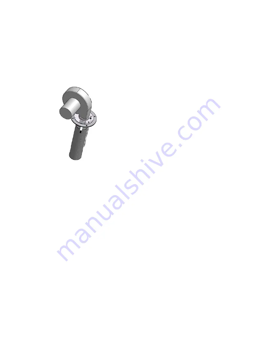
Figure 20 – Fan, Burner, Hot Surface Igniter and Flame
Sensor Arrangement
DynaFlame uses a sealed air fan to provide combustible
air/gas mix to the burner and push the products of
combustion through the heat exchanger and venting
system. The fan assembly consists of a sealed housing and
fan wheel constructed from spark resistant cast aluminum.
The fan is operated by a fully enclosed 230 VAC, 3 Phase
electric motor. The fan housing and motor assembly is fully
sealed and SHOULD NOT be field serviced. The power
draw of the motor is proportional to the modulated gas input
rate of the appliance.
7.4 INNER
JACKET
The inner jacket assembly is constructed from a special
corrosion resistant stainless steel. This includes both the
primary heat exchanger chamber and the secondary heat
exchanger chamber. All screws and fasteners used for
assembly
of the inner jacket and secondary heat exchanger
chamber are also stainless steel.
DO NOT mix stainless steel and standard plated
fasteners when disassembling and reassembling the
inner jacket sheet metal components. Standard plated
fasteners will be damaged by the flue product
condensate when used on the inner jacket assemblies.
7.5
OUTER JACKET
The outer jacket assembly is constructed from mirror finish
stainless Steel. This ensures a long life for the jacket
assembly, with full integrity
7.6
VENTING TRANSITION
All appliances are shipped with a rectangular to round
stainless steel adapter. Depending on the appliance
category an increaser will be required for the proper vent
configuration. Please refer to table #3 dimensions and
specifications.
When installing Category II or IV appliances care must be
taken to properly seal all joints and provide slope for
drainage of condensate.
PART 8
FIELD STARTUP
PROCEDURE
8.1 CHECKING
THE
INSTALLATION
•
Inspect the connections for water, gas and electricity.
•
Confirm that water is being pumped toward the heat
exchanger inlet. Never pump away from the exchanger
since this will result in a low-pressure zone, which will
allow localized boiling and result in heat exchanger
damage.
•
Power to the boiler and pump must be from the same
circuit to prevent the boiler firing in case the pump is
inadvertently shut off.
•
Inlet gas pressure must be a minimum of 3” W.C. for
natural gas and 11” W.C. for propane.
•
With the boiler off, open the main gas supply valve and
vent the trapped air from the piping leading to the
boiler. Confirm that all gas connections to the heater
are tight and that there are no missing test plugs.
•
Connect a manometer to obtain the differential air
pressure between negative and positive ports. See
Figure #3.
•
The air/gas ratio controller automatically adjusts to
match the air signal on the gas side. In this way true
mass flow control of air/gas mix is achieved. Typical
differential air settings are listed in Table 8. All boilers
are test fired and factory set. A test sticker with actual
reading is affixed to the unit. In general, these readings
will be within 0.3” W.C. of the readings shown in
Table 8.
Refer to Part 3 of the manual for recommendations on
setting combustion characteristics.
8.2 CHECKING
THE
CONSTRUCTION
•
Check the boiler wiring to see that it agrees with the
wiring diagram supplied.
•
Confirm that all terminal strips and field connections
are identified.
•
Confirm that the SmartFlame control is set in the
proper mode. In remote mode an external controller
determines the set point and the stage contacts on the
SmartFlame are always closed. Auto reset limits are
fixed in all Modes.
•
With the firing valve in the off position, switch on power
to the boiler. The indicator lights will sequentially
energize to show that the operator, limit control and
water flow are functioning properly. The fan motor will
accelerate until the airflow light energizes. If a light
remains off, the ignition sequence will not proceed.
During trial for ignition the red flame failure light may
light up momentary.
•
Once all lights are energized the ignition module will try
for ignition. When the igniter is hot enough, the ratio
gas valve actuator is energized and if ignition is
accomplished the blue main burner light will come on
and remain lit. If ignition is not accomplished, the red
flame failure light will energize and two more ignition
trials will be made 15 seconds apart. The control will
then proceed to lockout and must be reset by
momentarily interrupting power. It is normal during
Содержание DFH500
Страница 31: ...28 PART 9 TROUBLE SHOOTING ...
Страница 32: ...29 ...
Страница 39: ...36 PART 12 EXPLODED VIEW ...
Страница 40: ...37 ...
Страница 41: ...38 ...
Страница 46: ...43 PART 13 ELECTRICAL DIAGRAMS ...
Страница 47: ...44 ...
Страница 48: ...45 ...
Страница 49: ...46 ...
Страница 50: ...47 ...
Страница 51: ...48 ...


