


16
•
Turn the power switch to “ON” position.
•
Adjust the thermostat temperature set point to the desired
water temperature so the appliance will call for heat.
•
Check appliance performance by cycling the system while
you observe burner response. The burner should ignite
promptly. Flame pattern should be stable, see
“Maintenance-Normal Flame Pattern.” Turn system off and
allow burner to cool, then cycle burner again to ensure
proper ignition and flame characteristics.
IMPORTANT
Upon completion of any testing on the gas system, leak test all
gas connections with a soap solution while the main burner is
firing. Immediately repair any leak found in the gas train or
related components. DO NOT operate an appliance with a leak
in the gas train, valves or related gas piping.
3.7.1
Regulated Gas Supply Pressures for DynaFlame®
Boilers & Water Heaters
A stable gas supply pressure is extremely important to avoid
rough starts with machines like the DynaFlame® which use a 1
to 1 ratio control valve for internal gas pressure regulation.
Camus® requires that all DynaFlame® models equipped with
the SKP25 be supplied with no more than 1 PSI incoming
supply pressure. This means that lockup pressure must not
exceed 1 PSI. For models NOT incorporating the SKP25
lockup pressure must not be in excess of 14” w.c.
It is paramount that maximum lockup pressure be confirmed
before any attempt is made to start up the appliance.
A suitable lockup regulator with internal or external relief will
not exceed running pressure by more than 20%, which means
that the regulator must be capable of rated gas flow with a
maximum running supply pressure of 7.5” W.C.
When required the boiler should be installed with a final stage
gas regulator that is to be located as close as possible but no
more than 10 feet from the appliance.
It is paramount that maximum lockup pressure be confirmed
before any attempt is made to start up the appliance.
Operating the DynaFlame® at lockup pressures exceeding the
recommended levels can lead to delayed ignitions and damage
to the appliance.
3.8
CHECKING DIFFERENTIAL AIR AND GAS
PRESSURES (DF2000 - DF6000)
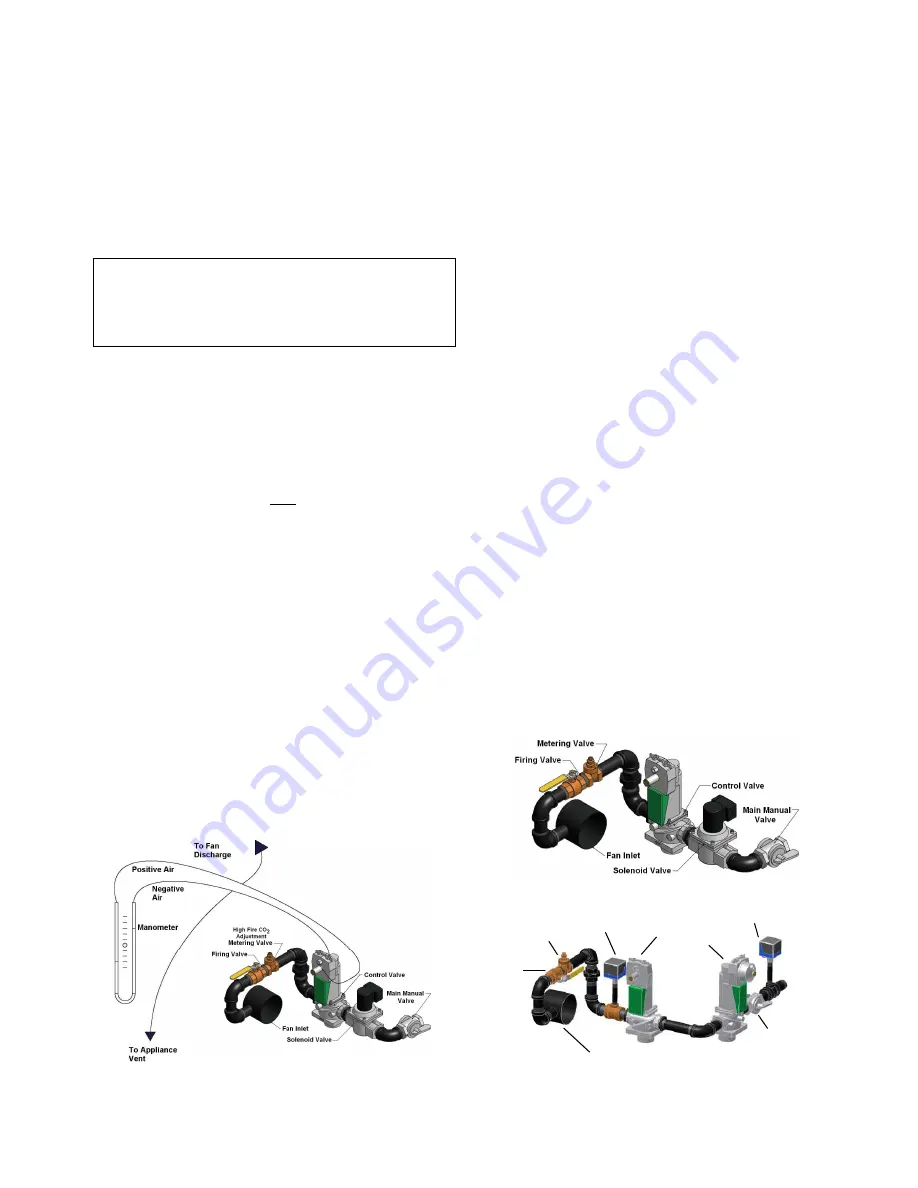
Figure 11 – Differential Air Pressure Manometer
Connection
•
The 1 to1 air/gas ratio control actuator has embossed
markings identifying + air – air, + gas & - gas
connections. Using a test hose assembly fitted with
tees, connections can be made from the manometer
to the appropriate ports on the actuator.
•
Using tees connect a hose from the positive air and
the negative air to each of the two sides of a
manometer. This will allow the two pressure points to
be measured while at the same time the actuator still
receives the proper operating signal.
•
If a second manometer is available it can be
connected to the appropriate gas ports. Typically the
gas signal will closely follow the air signal on all
models. If the incoming gas pressure reduces
significantly as the Variable Frequency Drive (VFD)
accelerates to maximum speed the gas signal may
lag behind the air signal by up to 15%. This will occur
once the actuator has driven downwards as far as it
can go. The amount that the actuator has opened is
registered by an indicator arm which is visible through
the view window.
•
As the appliance comes on and fires, record the
maximum inches of water column which is achieved
at maximum speed on the VFD using start-up report
form (93-0130). To adjust this differential pressure
when commissioning the appliance, use the adjusting
screw on the air shutter to the fan. Readings are to
correspond to the values shown on the test sticker. In
all cases the final adjustment is to be made using a
combustion analyzer. Depending on field conditions
differential pressures will have to be adjusted
accordingly. Typically with long lateral runs the
differential signal as read will be reduced from the
value shown on the test sticker. The opposite will
occur with tall stacks where drafts exceed negative
0.15“W.C.
•
If the appliance will not light off and the blue ‘main
flame’ light is coming on but not staying on then it will
be necessary to adjust the low fire as explained in the
detailed start-up procedure.
3.9
GAS TRAIN AND CONTROLS
Figure 12: Typical Gas Train (DF2000 – 3000)
Figure 13: Typical Gas Train (DF 3500 – 6004)
Fan Inlet
Firing
Valve
Metering
Valve
Differential High
Gas Switch
Control Valve
Regulator Valve
Main Manual
Valve
Low Gas Switch
Содержание DFH/W500
Страница 2: ......
Страница 40: ...35...
Страница 71: ...66 PART 12 EXPLODED VIEW...
Страница 72: ...67 3 44 10 45 46 47 28 31 26 52 57 58 59 54 60 61 SOLA Control Panel 39 4...
Страница 82: ...77 PART 13 ELECTRICAL DIAGRAMS...
Страница 83: ...78...
Страница 85: ...80...
Страница 86: ...81...
Страница 87: ...82...


