42
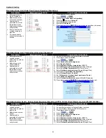
4-20mA/ 0-10Vdc Setpoint Operation (Standalone)
Description
Electrical Connection(s)
Programming Instructions
Boiler operates with
variable setpoint
determined by 4-20mA
incoming signal
Modulates on boiler
inlet sensor (default)
Heat demand is
generated when inlet
temperature drops
below setpoint minus
on hysteresis and 4-
20mA or 0-10Vdc signal
is present.
If set to local enable
constant pumping is
required
For remote enable
intermittent pumping is
allowed.
1)
Place toggle switch to
LOCAL
2)
Press
and
3)
Press
[CH
– Central Heat Configuration]
4)
Press the to arrive at
Setpoint
5)
Select
Setpoint Source = S2 (J8-6) 4-20mA
6)
Select
4mA water temperature
7)
Select
20mA water temperature
8)
Place toggle switch to
REMOTE
for remote operation (if required)
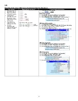
4-20mA/ 0-10Vdc Firing Rate Operation (Standalone)
Description
Electrical Connection(s)
Programming Instructions
Boiler operates with
variable firing rate
determined by 4-20mA
incoming signal
Modulates on boiler
inlet sensor (default)
Heat demand is
generated when inlet
temperature drops
below setpoint minus on
hysteresis and 4-20mA
or 0-10Vdc signal is
present.
If set to local enable
constant pumping is
required
For remote enable
intermittent pumping is
allowed.
1)
Place toggle switch to
LOCAL
2)
Press
and
3)
Press
[CH
– Central Heat Configuration]
4)
Press the to arrive at
Modulation
5)
Select
Modulation Rate Source = S2 (J8-6) 4-20mA and burner on/off
6)
Place toggle switch to
REMOTE
for remote operation (if required)
Содержание ADVANTUS AVH 500
Страница 2: ......
Страница 3: ......
Страница 38: ...31 Figure 23 Recommended Piping with Reverse Return and Variable Primary Flow...
Страница 70: ...63 Figure 44 Typical Gas Train Models AV1000 3000 Figure 45 Typical Gas Train Models AV3500 4000...
Страница 88: ...81 PART 12 EXPLODED VIEW Figure A...
Страница 89: ...82 Figure B FAN BURNER ASSEMBLY AV500 600 some items may not be as shown...
Страница 90: ...83 Figure C FAN BURNER ASSEMBLY AV800 4000 some items may not be as shown...
Страница 91: ...84 Figure D Figure E...
Страница 92: ...85 Figure F Figure G...
Страница 93: ...86 Figure H CONTROL BOARD ASSEMBLY...
Страница 100: ...93 PART 13 ELECTRICAL DIAGRAMS...
Страница 101: ...94...
Страница 102: ...95...


