background image

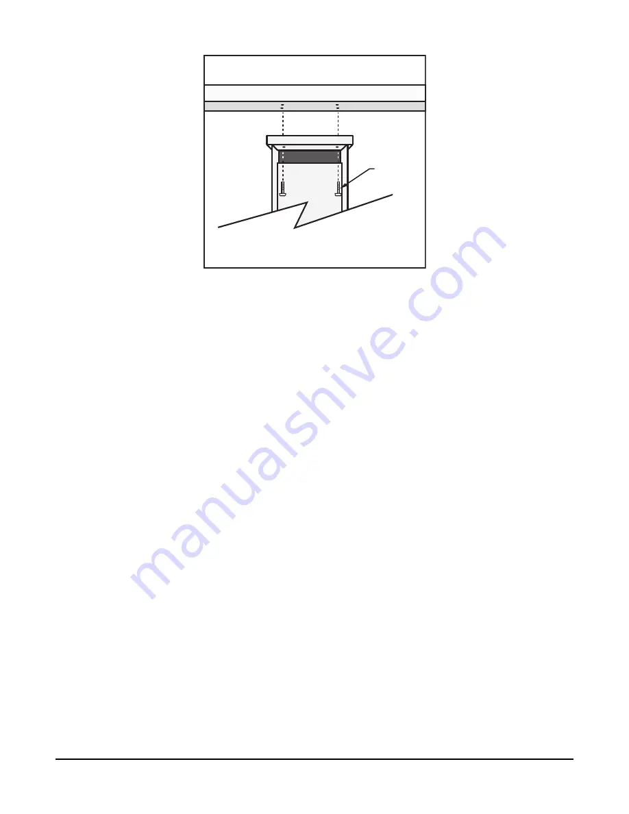
Screws 
(4)

FIGURE 6-7. T107 crossarm mounting

1. Adjust the bolts at the base of the pole to vertically level the top section of the mounting

pole.

2. Remove the front lid and the protective connector cover from the back of the enclosure by

loosening the one Phillips screw at the bottom of the cover.

3. Place the crossarm on top of the enclosure, lining up the four threaded holes on the

underside of the arm with the four holes in the top of the enclosure.

4. Attach the arm to the enclosure by inserting and tightening four Phillips head screws

(

FIGURE 6-7

(p. 21)).

5. Adjust the position of the enclosure so that the crossarm is oriented along a due north to

due south axis with the rain gage and solar radiation sensor (pyranometer) on the south
side for northern latitudes and the reverse for southern latitudes.

6.6 Sensor installation

The following components included with the T107 are used for this installation procedure:

(1) T107 crossarm with sensors (

FIGURE 6-8

(p. 22))

(1) Met One 034B or WindSonic wind sensor

(1) White mounting shaft for 034B or WindSonic

(1) Radiation shield

Section 6. Installation

21

Содержание T107

Страница 1: ...Revision 08 2019 Copyright 1993 2019 Campbell Scientific Inc Product Manual...

Страница 2: ...ucts to CSI CSI will return such Products by surface carrier prepaid within the continental United States of America To all other locations CSI will return such Products best way CIP port of entry per...

Страница 3: ...ing address is CAMPBELL SCIENTIFIC INC RMA _____ 815 West 1800 North Logan Utah 84321 1784 For all returns the customer must fill out a Statement of Product Cleanliness and Decontamination form and co...

Страница 4: ...work l Wear a hardhat and eye protection and take other appropriate safety precautions while working on or around tripods and towers l Do not climb tripods or towers at any time and prohibit climbing...

Страница 5: ...6 3 1 Pole grounding 18 6 4 Enclosure installation 19 6 5 Crossarm installation procedure 20 6 6 Sensor installation 21 6 6 1 RH and temperature radiation shield installation procedure 22 6 6 2 034B...

Страница 6: ...bles 56 6 12 Sealing and desiccating the enclosure 57 6 13 T107 software 58 7 Maintenance and troubleshooting 60 7 1 Maintenance 60 7 1 1 Pole maintenance 60 7 1 2 Power supply maintenance 60 7 1 3 De...

Страница 7: ...nd sensor orientation 76 A 1 Online magnetic declination calculator 78 Appendix B T107 maintenance log 80 Appendix C PS24 24 Ah power supply with 10 x 12 inch enclosure 83 C 1 PS24 components 83 C 2 P...

Страница 8: ...ions A properly programmed station calculates potential evapotranspiration ETo which is the amount of water lost from the soil due to evaporation and plant transpiration Calculating the evapotranspira...

Страница 9: ...emove the yellow cap from the RH and temperature sensor the red or green cap from the pyranometer and the rubber band from the tipping bucket mechanism Save the caps for shipping or storing the sensor...

Страница 10: ...down lengthwise on a floor or table top 3 Position the box as shown in FIGURE 3 1 p 3 4 Cut the tape along the edge of the lower flap first FIGURE 3 1 p 3 FIGURE 3 1 Cut flap packing tape 5 Cut the t...

Страница 11: ...t any shortages 8 Securely tape box shut if transporting entire station to another site 9 If at the main site remove communication components that are installed at the calling computer Repackage remai...

Страница 12: ...FIGURE 3 4 T107 bottom layer Section 3 Initial inspection 5...

Страница 13: ...7 pole Pole installation p 16 4 Place instrumentation enclosure on the T107 pole slide the enclosure to the top of the pole and secure it with the correct orientation Enclosure installation p 19 5 Ins...

Страница 14: ...ion and maintenance Lock and key for enclosure Magnetic declination angle Magnetic compass Straight bit screwdrivers small medium large Phillips head screwdrivers small medium Small diagonal side cutt...

Страница 15: ...it Drill with 6 mm 7 32 in drill bit 4 2 Supplies for power and communications options AC Power Wire conduit and junction boxes as needed FIGURE 4 1 p 8 FIGURE 4 1 T107 pole installation with currentl...

Страница 16: ...ve conductors total to travel from the weather station to the central computer junction box Direct burial armored cable may be required for rocky soils or rodents Anixter pn F 02P22BPN phone 847 677 2...

Страница 17: ...rom the influence of obstructions such as buildings and trees The weather station should not be located where sprinkler irrigation water will strike sensors or instrument enclosure Some general guidel...

Страница 18: ...adiation and adequately ventilated Situations to avoid include l large industrial heat sources l rooftops l steep slopes l sheltered hollows l high vegetation l shaded areas l swamps l areas where sno...

Страница 19: ...n 51 6 9 Solar panel installation 53 6 10 Battery installation 55 6 11 Restraining cables 56 6 12 Sealing and desiccating the enclosure 57 6 13 T107 software 58 6 1 Base foundation installation The fo...

Страница 20: ...f the conduit Make certain the cavity points in the direction from which power and communications cables will come For example the cavity will point towards a valve box if one is being used 6 Center t...

Страница 21: ...finish 13 Wait 24 hours before removing the concrete form 14 Wait seven days before mounting the pole 6 2 AC power installation procedure The AC power option includes a 100 to 240 VAC to 24 VDC power...

Страница 22: ...y to the T107 enclosure according to local electrical codes 6 Splice the incoming two conductor cable to the power cable provided with the station Use the direct burial splice kit when splices are in...

Страница 23: ...bulkhead connectors 6 3 Pole installation The following components included with the T107 are used for this installation procedure 1 top pole section tapered 1 base pole section 6 5 8 inch washers Sec...

Страница 24: ...he pole is designed to withstand winds of 45 m s 100 mph The lightning rod assembly is attached after the instrumentation enclosure is installed Use the following procedure to attach the pole to the b...

Страница 25: ...ot have power or communication cables 8 Place the white pole cap over the pole end 9 Raise the pole on a still day 10 Place a washer on top of the two nuts on each foundation bolt 11 Taking care not t...

Страница 26: ...cm 1 in of insulation from both ends of the 4 AWG ground cable 4 Strip 3 cm 1 in of insulation from the lower end of the 10AWG ground wire 5 Loosen the set screw on the lug and insert the 4 AWG and 10...

Страница 27: ...ure so it faces east for northern latitudes or west for southern latitudes The top of the enclosure should be 2 to 2 5 cm 3 4 to 1 in above the top of the pole FIGURE 6 6 p 20 FIGURE 6 6 Enclosure spa...

Страница 28: ...osure 4 Attach the arm to the enclosure by inserting and tightening four Phillips head screws FIGURE 6 7 p 21 5 Adjust the position of the enclosure so that the crossarm is oriented along a due north...

Страница 29: ...emperature radiation shield installation procedure 1 Remove the two knurled thumb screws taped underneath the crossarm 2 Remove the yellow shipping cap from the end of the temperature relative humidit...

Страница 30: ...re relative humidity into the radiation shield until it stops 4 Attach the radiation shield to the underside of the crossarm using the two knurled thumb screws from step 1 5 Plug cable into the TEMP R...

Страница 31: ...ensor wind sensor option MW Do the following to install the 034B Wind Sensor after the crossarm is securely installed FIGURE 6 11 p 24 FIGURE 6 11 Wind and RH temperature sensor installation Section 6...

Страница 32: ...time 4 Insert the mounting shaft through the U bolt on the crossarm 5 Adjust the mounting shaft so that the cable and connector coming out the end of the crossarm can plug easily into the mating conne...

Страница 33: ...etely seated on the connector and the locking ring is turned a quarter revolution clockwise WARNING Plugging this sensor into the SDI 12 connector can damage this sensor the main enclosure connector b...

Страница 34: ...e the electronics cover to expose the printed circuit board PCB FIGURE 6 14 p 27 FIGURE 6 14 Removal of the electronics cover 5 Move the jumper at the top of the PCB so that it is placed over the cent...

Страница 35: ...osure cover 6 6 3 2 WindSonic attachment to crossarm 1 Remove the three Phillips screws from the end of the white mounting shaft 2 Remove the protective cap covering the WindSonic sensor cable plug 3...

Страница 36: ...ide the connector and cable up through the center of the mounting shaft 5 Plug the cable into the sensor The connector has a key and needs to be pushed in then rotated clockwise to lock it in place FI...

Страница 37: ...es true north Determining True North and wind sensor orientation p 76 9 Space the sensor about 25 cm 10 in above the crossarm and tighten down the U bolt 10 Plug the cable into the Temp Sonic connecto...

Страница 38: ...eeded to get the bubble level centered 4 Put the gold funnel back on the top of the rain gage after leveling has been completed 5 Plug the cable in the RAIN PRECIP connector on the enclosure Ensure th...

Страница 39: ...FIGURE 6 19 Pyranometer leveling 2 Remove the red or green shipping cap from the pyranometer FIGURE 6 20 p 32 FIGURE 6 20 Remove red or green pyranometer cap Section 6 Installation 32...

Страница 40: ...nsor cables match the labeling on the back of the enclosure For more information refer to Sensor schematics p 69 CAUTION Each plug must be completely seated on to the connector and the locking ring tu...

Страница 41: ...ther station program to the station using Campbell Scientific software such as VisualWeather PC400 or LoggerNet a The station can be accessed directly using a CR1000KD keypad display at the weather st...

Страница 42: ...for the data logger in the T107 station l PakBus address 1 l RS 232 Port Autobaud 300 to 115 200 bps l ME Autobaud l SDC7 or SDC8 115 200 bps 6 7 1 Direct connect to T107 station The T107 station does...

Страница 43: ...2 Phone modem Phone modems enable communications between the T107 enclosure and a Hayes compatible modem at your computer over a dedicated phone line Phone line surge protection is built into the encl...

Страница 44: ...ing bracket 4 Screws 1 130 cm 12 in 14 AWG ground wire Use the following procedure to install the phone modem FIGURE 6 23 p 37 FIGURE 6 23 Phone modem mounting and connections battery not shown 1 Atta...

Страница 45: ...to the silicone gel inside the splice tube to be waterproof 6 7 3 Short haul modem Short haul modems enable communication between a data logger and computer over two twisted pairs of wires The maximum...

Страница 46: ...Mount the Rad SC932C mounting bracket into the enclosure with the three pre threaded screws provided 2 Connect the Rad modem and SC932C 3 Strap them into the mounting bracket under the Velcro strap 4...

Страница 47: ...al installation of short haul modem FIGURE 6 25 Short haul modem wiring diagram Components of the short haul kit used for external connections at the T107 enclosure are 1 6 m 20 ft 4 wire patch cable...

Страница 48: ...user supplied cable from the remote splice to the surge protector Connect it and the 1 5 m 5 ft patch cable to the surge protector 6 7 4 Radio Radios enable wireless communication between a data logge...

Страница 49: ...ours before damaging the battery A station with a 10 watt panel would need at least three hours of sunlight every day to keep the battery charged Recommendation here would be to decrease the power out...

Страница 50: ...ount the bracket and radio inside the enclosure using the three existing screws FIGURE 6 26 p 43 2 Thread the smaller SMA connector end of the internal antenna cable underneath the battery cables and...

Страница 51: ...s steel washers 4 8 mm 5 16 in stainless steel lock washers 4 black UV resistant wire ties 1 Remove the sensor cable cover off of the back of the enclosure by loosening the thumb screw at the bottom o...

Страница 52: ...lt to attach the adjustable angle mounting bracket to the pole Depending on the size of the antenna position the bracket directly below or above the enclosure top mounting bracket The top of an omnidi...

Страница 53: ...ow the angle bracket to rotate around the pole FIGURE 6 31 Antenna bracket mounted to pole 7 Mount the saddle bracket to the adjustable angle mount bracket by inserting the ends of the bracket through...

Страница 54: ...of the Yagi antenna into the saddle bracket b If the Yagi antenna at the station is communicating with an omnidirectional antenna at the base align the tines on the Yagi antenna so they are vertical F...

Страница 55: ...end of the cable Take the cover off when you re done f Use one of the black wire ties to strap the antenna cable to the bundle of sensor cables g Tighten up the wire ties holding the antenna cable to...

Страница 56: ...cable to Yagi antenna and to pole j Wire tie the antenna cable to the pole FIGURE 6 35 Wire tie locations for omnidirectional antenna installation k Clean up the wire ties and put the cable cover back...

Страница 57: ...ith the FCC RF exposure requirements the radio may be used only with approved antennas that have been tested with this radio and a minimum separation distance of 8 inches 20 cm must be maintained from...

Страница 58: ...rod installation Install lightning rod as shown in FIGURE 6 38 p 52 and FIGURE 6 39 p 52 1 Carefully mount the lightning rod clamp to the top of the pole FIGURE 6 38 p 52 Position the clamp so it won...

Страница 59: ...rip 2 5 cm 1 in from the top of the main green 10 AWG pole ground wire 3 Insert the exposed wire into the empty clamp opening Do not tighten the screw at this time FIGURE 6 39 p 52 FIGURE 6 39 Groundi...

Страница 60: ...Tighten the screw to hold the rod firmly in place 6 9 Solar panel installation FIGURE 6 40 Solar panel mounting and cabling 1 Mount the solar panel to the pole using the mounting brackets FIGURE 6 40...

Страница 61: ...ngle 3 After determining the tilt angle loosen the two bolts that attach the mounting bracket to the panel 4 Adjust the angle and tighten the bolts 5 Secure the wire to the mast using wire ties FIGURE...

Страница 62: ...5 4 Plug the battery wire into the connector 5 Put the cover back on the PS150 and latch it in place NOTE Do not switch the power supply ON until AC or solar power has been connected to the back of th...

Страница 63: ...ables 1 Loosely wire tie power communication and grounding cable to the wire tie harness at the top of the back of the station FIGURE 6 44 p 56 Do NOT clip back the wire tie at this time FIGURE 6 44 C...

Страница 64: ...over in place 3 Tighten the wire ties holding the cables to the wire tie harness and clip off excess ties FIGURE 6 45 p 57 6 12 Sealing and desiccating the enclosure The T107 enclosure is supplied wit...

Страница 65: ...ro straps 3 Close the enclosure hasp securely A padlock may be used on the latch for extra security FIGURE 6 46 Desiccant installation 6 13 T107 software A variety of different software packages are a...

Страница 66: ...loaded from the Campbell Scientific website www campbellsci com downloads VisualWeather version 3 0 or higher is designed to work with the T107 station and can be used to create programs monitor prese...

Страница 67: ...ed and maintenance that was performed 7 1 1 Pole maintenance Periodically check the pole for structural damage proper alignment and for level plumb 7 1 2 Power supply maintenance Rechargeable power su...

Страница 68: ...pyranometer carefully when cleaning Be careful not to scratch the surface of the sensor l Do a visual audio inspection of the 034B ET anemometer at low wind speeds Worn bearings can cause the wind cup...

Страница 69: ...distributor for service l Replace reed switch the 034B ET if needed Contact your local Toro distributor for service l Check calibration of the HMP60 ETS Temp RH sensor which tends to drift up over ti...

Страница 70: ...oro distributor for service Sensor cannot be calibrated in the field Some users recommend calibrating this sensor on a yearly basis 4 to 5 years l Check sensor cables as well as all other cables for c...

Страница 71: ...source the module measures the voltage of the lithium battery daily This voltage is displayed in the status table A new battery will have approximately 3 6 volts The data logger Status Table has a Li...

Страница 72: ...p 55 2 Use a voltmeter to measure the voltage on the 12V and G terminals FIGURE 6 43 p 56 the voltage must be from 9 6 to 16 VDC 3 Use a voltmeter to measure the voltage on the 5V and G terminals FIGU...

Страница 73: ...between 4 9 and 5 1 VDC 4 Make sure the data logger is connected to the communication peripheral and the communication peripheral is properly installed and configured Communication peripherals p 35 At...

Страница 74: ...program may need to be changed 6 Inspect the sensor for damage and or contamination If damaged contact your local Toro distributor for repair or purchase of a replacement sensor 7 2 4 WindSonic1 ET di...

Страница 75: ...Table 7 2 WindSonic Diagnostic Codes Diagnostic Status Comment 9 ROM error Read Only Memory checksum failed 10 Maximum Gain Questionable wind measurements Section 7 Maintenance and troubleshooting 68...

Страница 76: ...he pinned connectors on the cables Socketed connectors on the back of the enclosure are the mirror images of what s shown 8 1 Sensor schematics Schematics of T107 sensors and associated connectors are...

Страница 77: ...FIGURE 8 2 Schematic of 034B ET Wind Speed and Direction Probe and connector WS WD Section 8 Schematics of connectors 70...

Страница 78: ...FIGURE 8 3 Schematic of WindSonic1 ET Wind Sensor and connector Temp Sonic Section 8 Schematics of connectors 71...

Страница 79: ...FIGURE 8 4 Schematic of CS305 ET Solar Radiation Sensor and connector Solar Radiation Section 8 Schematics of connectors 72...

Страница 80: ...FIGURE 8 5 Schematic of TE525 ET Rain Sensor and connector Rain Precip 8 2 Power schematics FIGURE 8 6 Schematic of solar panel and connector Power Section 8 Schematics of connectors 73...

Страница 81: ...8 3 Communication modems schematics FIGURE 8 7 Schematic of short haul or phone modem and connector COMM Section 8 Schematics of connectors 74...

Страница 82: ...hods of Observation World Meteorological Organization No 8 5th edition Geneva Switzerland The State Climatologist 1985 Publication of the American Association of State Climatologists Height and Exposu...

Страница 83: ...web calculator Online magnetic declination calculator p 78 A general map showing magnetic declination for the Conterminous United States is shown in FIGURE A 1 p 76 FIGURE A 1 Magnetic declination for...

Страница 84: ...10 June 2006 is 2 68 and True North is 0 2 68 or 2 68 as read on a compass FIGURE A 2 A declination angle east of True North positive is subtracted from 360 0 degrees to find True North FIGURE A 3 A...

Страница 85: ...tude by entering the Zip Code or the Country and City and then clicking the Get Add Lat Lon button FIGURE A 4 p 78 Click the Calculate button to get the magnetic declination FIGURE A 4 NOAA web calcul...

Страница 86: ...FIGURE A 5 NOAA calculated declination using HTML result format Appendix A Determining True North and wind sensor orientation 79...

Страница 87: ...ndix B T107 maintenance log Sensor installation date _______________________________ Clean inspect rain gage sensor recommended weekly Date OK comments Date OK comments Appendix B T107 maintenance log...

Страница 88: ...Clean inspect rain gage sensor recommended weekly Date OK comments Date OK comments Clean inspect solar radiation sensor recommended monthly Date OK comments Appendix B T107 maintenance log 81...

Страница 89: ...switch recommend yearly Date OK comments Replace RH chip in the HMP60 ETS temp RH sensor recommended yearly Date OK comments Replace desiccant bags qty 2 inside enclosure recommended yearly Date OK co...

Страница 90: ...environmental enclosure FIGURE C 1 p 84 through FIGURE C 3 p 85 Typically the PS24 is ordered without a charging regulator and the PS100 or PS150 is moved from the station enclosure to the PS24 enclos...

Страница 91: ...FIGURE C 1 PS24 enclosure with PS150 and battery bracket FIGURE C 2 24 Ah battery and battery cable Appendix C PS24 24 Ah power supply with 10 x 12 inch enclosure 84...

Страница 92: ...1 Place the top enclosure bracket on the pole at approximately 10 m 3 ft above the bottom of the pole The bracket should be installed with the hook side up and facing north 2 Slide the strut clamps in...

Страница 93: ...et might have to be moved a little to accept the enclosure bracketing so don t tighten the bracket yet FIGURE C 5 p 86 shows the top and bottom brackets correctly positioned on the T107 pole FIGURE C...

Страница 94: ...een the top lip of the bottom strut mount bracket and the notch directly below Move the bottom bracket if necessary then bolt the bottom bracket down see FIGURE C 7 p 88 CAUTION Do NOT over tighten th...

Страница 95: ...h the mechanism and slide it to the left Once in place put a small wire tie in the hole to the right of the locking mechanism FIGURE C 8 p 89 NOTE To remove the enclosure from the bracketing cut off t...

Страница 96: ...IGURE C 8 Enclosure locking mechanism 7 Install the solar panel above the PS24 enclosure and face the solar panel south FIGURE C 9 p 90 Appendix C PS24 24 Ah power supply with 10 x 12 inch enclosure 8...

Страница 97: ...d It doesn t hurt to leave a loop of cable inside the enclosure 10 If this is a station retrofit remove the PS100 or PS150 from the weather station enclosure and install it into the PS24 enclosure Unp...

Страница 98: ...e it s wired into the CH150 PS100 or PS150 regulator NOTE The charging LED steady red on the PS100 or flashing green on the CH150 and PS150 indicates that the charging source solar panel or AC is prov...

Страница 99: ...or in the external enclosure to the T107 station enclosure has a two pin connector on one end and tinned wires on the other 13 Toggle the power switch on the regulator CH100 PS100 CH150 or PS150 to th...

Страница 100: ...plastic nut on the back of the station that holds the POWER connector in place Remove the old connector and replace it with the new one placing the foam washer inside the enclosure Tighten the plastic...

Страница 101: ...of desiccant inside of the enclosure 22 Stick the humidity indicator card on a wall inside of the enclosure CAUTION Pink on the humidity indicator card means it s time to change the desiccant Change...

Страница 102: ...cc Website www campbellsci cc France Location Vincennes France Phone 0033 0 1 56 45 15 20 Email info campbellsci fr Website www campbellsci fr Germany Location Bremen Germany Phone 49 0 421 460974 0...

Отзывы: