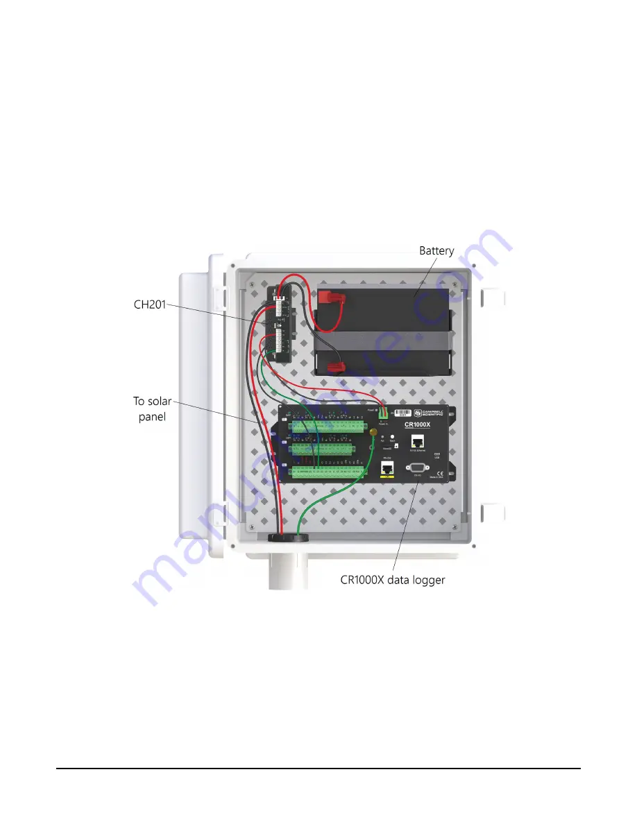
3. Connect the black (–) wire from the solar panel cable to the G terminal on the regulator
located between the DC IN 1 and DC IN 2 terminals. Connect the red (+) wire from the
solar panel power cable to the terminal labeled DC IN 1 on the regulator.
4. If charge current is available from the solar panel, the LED on the CH201 marked CHG will
begin to flash green. This indicates the battery is charging and verifies proper operation
and wiring of the regulator.
5. To supply power to the system, connect the red power wire from a data logger to either 12V
terminal on the CH201. Attach the black power wire from the data logger to one of the two
G terminals next to the 12V terminals.
FIGURE 3-21. CH201 wired to solar panel, CR1000X, and battery
SP50-L, SP90-L, and SP305-L Solar Panels
22


