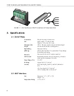
CS547 Conductivity and Temperature Probe and A547 Interface
11
3.
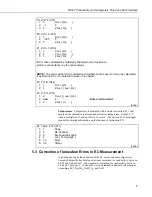
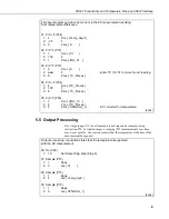
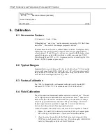
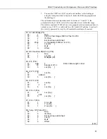
Connect the CS547 and A547 or probe and interface to the datalogger
using the wiring described in Section 4. Enter the following program into
the datalogger.
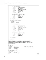
The calibration solution temperature must be between 1°C and 35°C; the
polynomial in step 11 (P58) corrects for temperature errors within this range.
The solution constant of 1.408 mS cm
-1
(for prepared solution mentioned above),
entered in step 13 (P37), is valid only for a 0.01 molal KCl solution. Location 8
[Kc (cm-1)], generated by step 14, will contain the resultant cell constant.
01: AC Half Bridge (P5)
01:
1
Rep
02:
15
2500 mV fast Range (5000 mV fast for 21X)
03:
2
IN Chan
04:
1
Excite all reps w/EXchan 1
05:
2500
mV Excitation (5000 mV for 21X)
06:
1
Loc [Rs ]
07:
1
Mult
08:
0
Offset
02: BR Transform Rf[X/(1-X)] (P59)
01:
1
Rep
02:
1
Loc [Rs ]
03:
1
Multiplier (Rf)
03: Z=F (P30)
01:
nnn
F
Enter Cable Length in Feet
02:
00
Exponent of 10
03:
5
Loc [Rp ]
04: Z=X*F (P37)
01:
5
Loc Rp
02:
.00032 F
03:
5
Loc [Rp ]
05: Z=X*F (P37)
01:
5
Loc Rp
02:
-.1
F
03:
5
Loc [Rp ]
06: Z=X+F (P34)
01:
5
Loc [Rp ]
02:
-.005
03:
5
Loc [Rp ]
07: Z=X+Y (P33)
01:
1
X Loc Rs
02:
5
Y Loc Rp
03:
1
Z Loc [Rs ]
08: Temp 107 Probe (P11)
01:
1
Rep
02:
3
IN Chan
03:
2
Excite all reps w/EXchan 2
04:
2
Loc [t]
05:
1
Mult
06:
0
Offset
(cont.)


