background image

1

CS547 Conductivity and Temperature
Probe and A547 Interface

1.  Overview

The CS547 conductivity and temperature probe, and A547 interface are designed
for measuring the electrical conductivity, dissolved solids, and temperature of
fresh water with Campbell Scientific dataloggers.  They require the use of AC
excitation, so they can be used with the CR10(X), 21X, and CR7 dataloggers but
not with the BDR301 or BDR320.  Use with multiplexers is possible.

Electrical conductivity (EC) of a solution is a simple physical property, but
measurements can be difficult to interpret.  This manual instructs the user how to
make EC measurements with the CS547.  Accuracy specifications apply to
measurements of EC in water containing KCl, Na

2

SO

4

, NaHCO

3

, and/or NaCl,

which are typical calibration compounds, and to EC not yet compensated for
temperature effects.

Statements made on methods of temperature compensation or estimating dissolved
solids are included to introduce common ways of refining and interpreting data, but
are not definitive.  Authoritative sources to consult include the USGS Water-Supply
Paper 1473, The pH and Conductivity Handbook published by OMEGA
Engineering, physical chemistry texts, and other sources.

1.1  EC Sensor

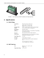
The EC sensor consists of three stainless steel rings mounted in an epoxy tube
as shown in Figure 4-1.  Resistance of water in the tube is measured by
excitation of the center electrode with positive and negative voltage.

This electrode configuration eliminates the ground looping problems associated
with sensors in electrical contact with earth ground.

Temperature is measured with a thermistor in a three wire half bridge
configuration.

1.2  A547 Interface

The interface contains the completion resistors and blocking capacitors.  The
interface should be kept in a non-condensing environment that is maintained
within the temperature range of the unit.

Содержание CS547

Страница 1: ...INSTRUCTION MANUAL CS547 Conductivity and Temperature Probe and A547 Interface Revision 9 00 C o p y r i g h t c 1 9 9 4 2 0 0 0 C a m p b e l l S c i e n t i f i c I n c...

Страница 2: ...in lieu of all other warranties expressed or implied including warranties of merchantability or fitness for a particular purpose CAMPBELL SCIENTIFIC INC is not liable for special indirect incidental...

Страница 3: ...2 2 3 Temperature Sensor 3 3 Installation 3 3 1 Site Selection 3 3 2 Mounting 3 4 Wiring 3 5 Programming 4 5 1 Programming Overview 4 5 2 Measurement Programming 4 5 3 Correction of Ionization Errors...

Страница 4: ...A547 Interface Table of Contents ii 9 Deriving a Temperature Compensation Coefficient 15 10 Instruction 11 Details 15 11 Electrically Noisy Environments 16 12 Long Lead Lengths Temperature 17 13 CS54...

Страница 5: ...cts Statements made on methods of temperature compensation or estimating dissolved solids are included to introduce common ways of refining and interpreting data but are not definitive Authoritative s...

Страница 6: ...1000 ft The sensor must be ordered with desired length as cable cannot be added to existing probes Depth Rating Maximum 1000 feet pH Range Solution pH of less than 3 0 or greater than 9 0 may damage t...

Страница 7: ...sensor parallel to the direction of flow In stilling wells and ground wells however diffusion rate of ions limits the response time 3 2 Mounting The stainless steel housing and sensor cable are made...

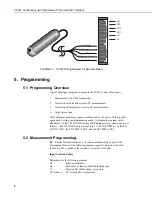
Страница 8: ...ing and programming needs All example programs in this manual are for the CR10 X and assume that datalogger wire connections are as follows the LO COND lead is connected to 1L the HI COND to 1H the EX...

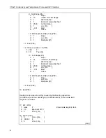
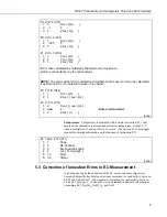
Страница 9: ...1 Mult 8 1 Offset 2 BR Transform Rf X 1 X P59 1 1 Reps 2 1 Loc Rs 3 1 Multiplier Rf Test the initial measurement to make a more accurate measurement 3 CASE P93 1 1 Case Loc Rs 4 If Case Location F P83...

Страница 10: ...Then Do 13 Full Bridge P6 1 1 Reps 2 14 250 mV Fast Range 3 1 DIFF Channel 4 1 Excite all reps w Exchan 1 5 2500 mV Excitation 6 1 Loc Rs 7 001 Mult 8 1 Offset 14 BR Transform Rf X 1 X P59 1 1 Reps 2...

Страница 11: ...e Temperature is measured with a single instruction P11 that measures the thermistor resistance and calculates temperature Output is C when a multiplier of 1 and an offset of 0 is used See Section 10...

Страница 12: ...4 Correction of Temperature Errors The effect of temperature on the sample solution can cause large errors in the EC measurement A simple method of correcting for this effect is to assume a linear re...

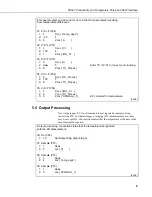
Страница 13: ...Y P38 1 7 X Loc lOO_Ct 2 8 Y Loc TC_Proces 3 9 Z Loc C25mScm_l EC corrected for temperature cont 5 5 Output Processing Over large ranges EC is not linear and is best reported as samples using instruc...

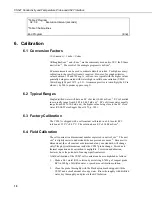
Страница 14: ...0 05 to 50 0 mS cm 1 the higher value being close to the EC of sea water USGS Water Supply Paper 1473 p 102 6 3 Factory Calibration The CS547 is shipped with a cell constant calibrated in a 0 01 molal...

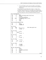
Страница 15: ...8 Kc cm 1 generated by step 14 will contain the resultant cell constant 01 AC Half Bridge P5 01 1 Rep 02 15 2500 mV fast Range 5000 mV fast for 21X 03 2 IN Chan 04 1 Excite all reps w EXchan 1 05 250...

Страница 16: ...X Loc 1 f t 02 1 408 F EC of calibration solution 03 7 Z Loc Act l Con 14 Z X Y P36 01 7 X Loc Act l Con 02 1 Y Loc Rs 03 8 Z Loc Kc cm 1 End 7 Maintenance Routine maintenance includes thoroughly clea...

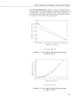
Страница 17: ...sate for ionization effects on the measurements Also shown is an ideal correction Factors were derived by measuring the standard solutions described in Section 2 2 with values of 0 0234 0 07 0 4471 07...

Страница 18: ...lated in Table 8 2 1 For the range of 0 to 50 C the interchangeability error is predominantly offset and can be determined with a single point calibration Compensation can then be done with an offset...

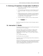
Страница 19: ...n as shown in the program segment in Section 5 4 10 Instruction 11 Details Understanding the details in this section are not necessary for general operation of the CS547 probe with CSI s dataloggers I...

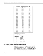
Страница 20: ...00 48 00 36465 47 91 50 00 33598 49 77 52 00 30983 51 59 54 00 28595 53 35 56 00 26413 55 05 58 00 24419 56 70 60 00 22593 58 28 TABLE 10 2 Polynomial Coefficients COEFFICIENT VALUE C0 53 4601 C1 9 08...

Страница 21: ...annel and input location assignments On the 21X and CR7 use the 15 mV input range and 4000 mV excitation 12 Long Lead Lengths Temperature If the CS547 has lead lengths of more than 300 feet use the DC...

Страница 22: ...52 283 C3 08 16 723 C4 09 2 211 C5 Proper entries will vary with program and datalogger channel and input location assignments On the 21X and CR7 use the 15 mV input range and 4000 mV excitation Use...

Страница 23: ...Probe and A547 Interface 19 FIGURE 13 2 A547 Interface Circuit Diagram EX TEMP EX COND COND TEMP SHIELD EX COND HI COND LO COND AG SE TEMP EX TEMP SHIELD Datalogger Connections Sensor Connections R2 1...

Страница 24: ...CS547 Conductivity and Temperature Probe and A547 Interface 20 This is a blank page...

Страница 25: ...This is a blank page...

Страница 26: ...campbellsci com br suporte campbellsci com br Campbell Scientific Canada Corp CSC 11564 149th Street NW Edmonton Alberta T5M 1W7 CANADA www campbellsci ca dataloggers campbellsci ca Campbell Scientifi...

Отзывы: