EN
Series DRCS drive for stepper motors
7
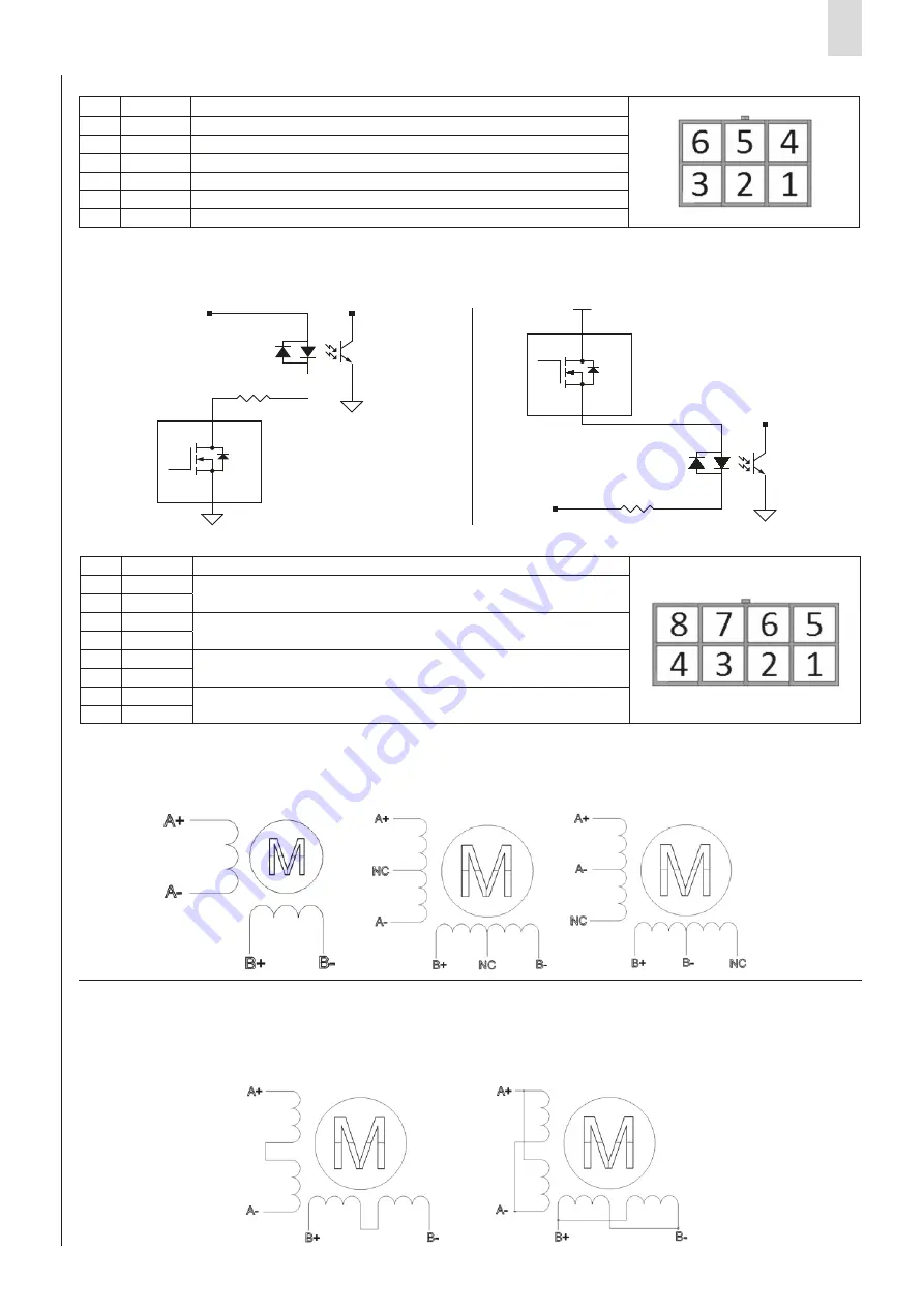
It is possible to connect two proximity switches, one for Homing functionality and another for various functions:
1. Extra stroke sensor
2. Stop movement command (use it for stop the movement before to reach the target position)
Is possible to use both NPN and PNP proximity switches.
Stepper motors can have 4- or 8- wire configurations; the following pictures show these configurations and the connections
for the most common types of Stepper motors. The motor must be connected to the MOTOR connector:
4-wire motor:
8-wire motor:
As shown in the following picture, the 8-wire motors permit two different connection schemes: series or parallel.
In the series connection scheme, the high-speed torque is lower, but the losses and operating temperature are also reduced.
With this scheme, it is recommended to decrease the phase current by at least 30%.
In the parallel connection scheme, the torque and speed of the motor follow the torque-speed characteristic curve.
7.3 Proximity connector
7.4 Motor connector
Pin
Signal
Description
1
+24V
+24V power for external proximity (ref.
GND
)
2
HMG
Input for Homing sensor
3
GND
Common (ref. for pin 1)
4
EXCOM1
Excom1 common (PNP=GND and NPN=+24V DC)
5
GND
Common (ref. for pin 1)
6
OPT
Input for Proximity / external stop (optional)
Pin
Signal
Description
1
B-
Motor phase B negative pole
2
B-
3
A-
Motor phase A negative pole
4
A-
5
B+
Motor phase B positive pole
6
B+
7
A+
Motor phase A positive pole
8
A+
3
4
2
1
EXcom1
Q
R46
2K2 5% 1/2W
3
4
Q
2
1
3
FINE CORSA NPN
+24V
FINE CORSA PNP
2
1
3
2
1
R46
2K2 5% 1/2W
Excom1
3
4
2
1
EXcom1
Q
R46
2K2 5% 1/2W
3
4
Q
2
1
3
FINE CORSA NPN
+24V
FINE CORSA PNP
2
1
3
2
1
R46
2K2 5% 1/2W
Excom1


