EN
Series DRCS drive for stepper motors
10
PROG.
TYP
COMMAND
FORCE [N]
max 54
POSITION [mm]
max 1500
VELOCITY [mm/s]
max 3333
ACC [mm/s
2
]
max 5000
DEC [mm/s
2
]
max 5000
1
pos. Absolute
0.000
100.000
500.000
100.000
100.000
CPU
2.0 GHz or higher
RAM
2 GB or higher
HD space
600 MB or higher
Communication port
USB 2.0
Operative system
Windows 7, Windows 8
Screen resolution
1280x720
The available outputs are:
- Ready (
RDY
): indica che l’azionamento DRCS è abilitato senza allarmi, ed è pronto a ricevere un comando di moto.
- Homing OK (
HOK
): indica che la procedura di Homing (ricerca della posizione dio zero) è stata completata correttamente.
- Motore in posizione (
POS
): indica che il movimento è stato eseguito correttamente e la posizione è stata raggiunta.
- Busy (
BSY
): indica che il motore si sta muovendo e non può ricevere un ulteriore comando.
- Allarme (
ALM
): indica uno stato di allarme; nella tabella di allarme sono riportate tutte le possibili cause di guasto.
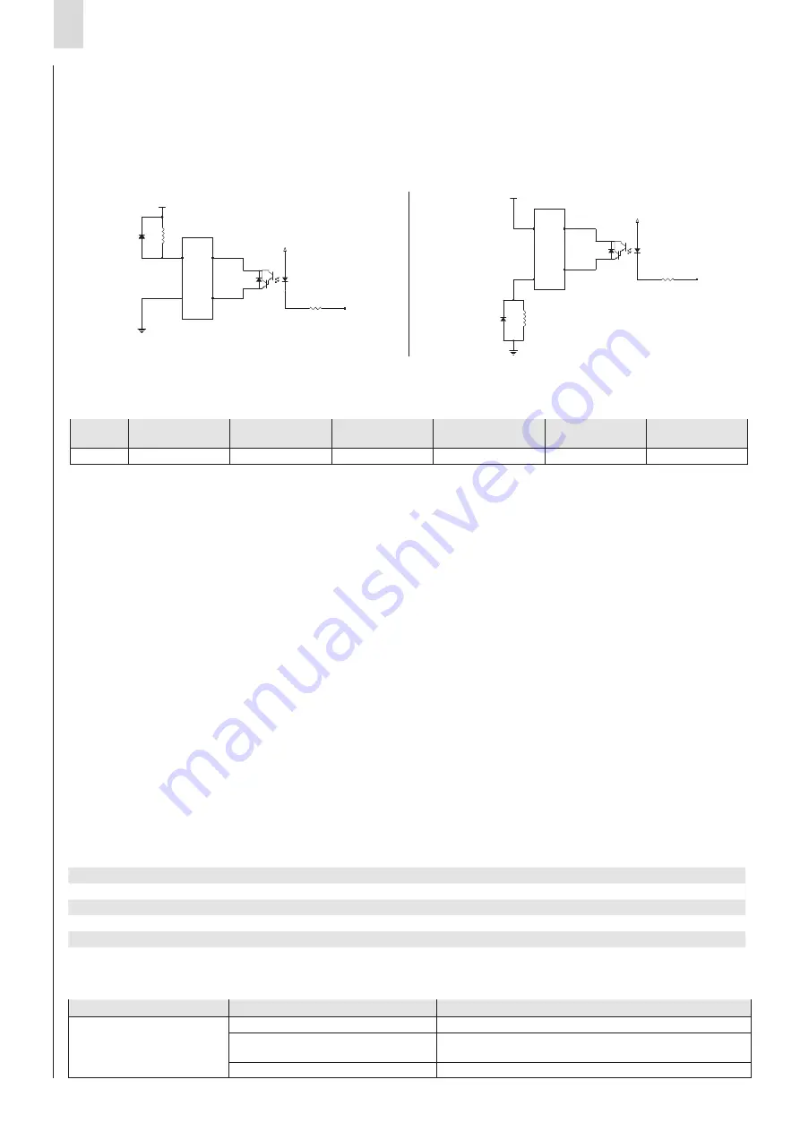
- Configurable output (
OUT+ and OUT-
): it is possible to set this output via the
QSet
software (for more details
on using the configurator, specifically this feature, refer to the manual) as either PNP or NPN type, as shown below.
7.10 Steps to realise a movement
• In
QSet
, configure one or more command lines and load them to the DRCS drive using the “PC to Drive” command.
Example: position 100 mm, velocity 500 mm/s, acceleration and deceleration 100 mm/s
2
entered into row 1:
- Enable the DRCS drive by setting the Enable input (
ENB
).
- Deactivate all digital inputs (from
IN0
to
IN6
) and verify, by observing the Ready output (
RDY
), that the DRCS drive is
ready. If yes, generate a pulse (minimum width of 2ms) on the Strobe input (
STB
); the Homing procedure then starts and
the Busy output (
BSY
) becomes active until the motion has ended.
- When the Homing procedure ends (refer to the Homing OK output (
HOK
), change the IN0 state to 1 and hold the inputs
IN1
÷
IN6
at 0.
- Verify the Ready output (
RDY
) value and, if the DRCS drive is ready, generate a pulse (minimum width of 2ms) on the
strobe input (
STB
).
- When the movement starts, the In Position output (
POS
) is deactivated and the Busy output (
BSY
) is activated until the
motion ends.
- When the motion ends, the In Position output (
POS
) becomes active, the Busy output (
BSY
) is deactivated.
• The user must adopt the necessary measures to prevent damage to the system caused by voltage spikes on the power lines
as a result of power outages of high-energy equipment.
• The DRCS board does have protection against reverse polarity of the power supply voltage.
• To improve noise immunity and prevent damage, it is recommended to connect the device to the system ground using any
of the holes in the aluminium body, and attaching the conductor to the metal plate.
• Only for models DRCS-XXX-X-C-X-X, it is possible to set the node address, its baud rate (up to 1 M/s) and enable the
CANopen communication mode (disabled by default) via the
QSet
configuration software (for more details on using the
configurator, specifically this feature, refer to the manual).
If the DRCS drive is the last node of the CANopen segment, it is necessary to use the termination resistor for the bus: the
order code EC-060623 is for a DRCS drive that has this resistor installed, which can be mounted on one of the two
CANopen connectors.
• To configure the DRCS drive, download the
QSet
software setup file from http://www.camozzi.com and proceed with
installation following the on-screen instructions. For more details, please refer to the
QSet
manual.
The connection to the DRCS drive is standard Micro USB (available as an accessory: G11W-G12W-2); communication
is only possible if the USB driver is correctly installed on PC.
The USB driver is installed automatically during the
QSet
installation.
7.11 PC requirements
• On start-up of the
QSet
software, the system verifies communication between the DRCS drive and the PC where the
configuration software is installed. In the event of communication failure, an error message is displayed.
Type of fault
Cause
Solution
Communication failure
between DRCS drive and PC
Power supply not connected
Connect the electrical power supply
USB cable not connected
Connect the USB cable to one of the ports available
on the PC and to the Micro USB connector
USB driver not installed
Contact the Camozzi technical assistance service
22
21
6
4
2
1
3V3
R62
180 5% 1/5W
+24V
NPN
A
K
22
21
6
4
2
1
3V3
R62
180 5% 1/5W
+24V
PNP
22
21
6
4
2
1
3V3
R62
180 5% 1/5W
+24V
NPN
A
K
22
21
6
4
2
1
3V3
R62
180 5% 1/5W
+24V
PNP


