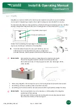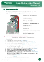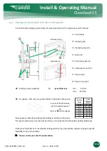
EMC_SPEC040_CLCR.doc
Rev. E
–
2021 10 18
34/63
Install & Operating Manual
CleanSeal V3
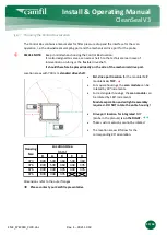
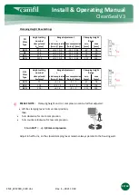
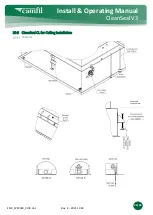
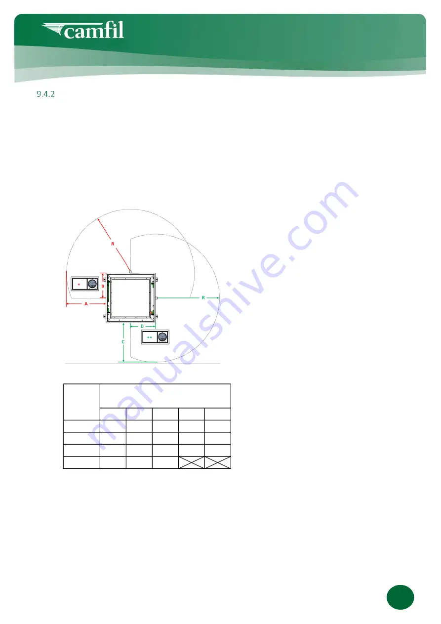
Choosing the Control Box Location
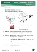
The Control Box contains a manometer for filter pressure drop and the interface for the scan
operation, i.e. the downstream sampling port and the mechanical drive port for the probe.
PLEASE NOTE:
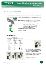
Keep in mind when choosing the Control Box location :
It is also designed to serve as an access hatch to the technical area in case of
intervention on tubing or the flexible drive shaft.
It should therefore be placed ideally on the side of the mechanical drive port.
•
Std. drive port location
for the
modular MIP
module
is on TOP
- .
•
For square housings, the
scan module
can be
rotated by 90° increments.
•
For rectangular housings, the
scan module
can
be rotated by 180° increments.
Module separation and airtight reassembly
required - DO NOT rotate the entire housing!
•
Drive port location for integrated
MIP
(probe in the plenum)
is on the RIGHT
- . .
•
These custom versions cannot be rotated.
•
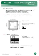
The location area will follow for the
corresponding 90° orientation.
Dimensions refer to the outer flanges.
➔
Please contact your Camfil representative
R
A
B
C
D
3P3
800
590
360
590
360
3P6
800
590
360
440
335
6P6
800
440
335
440
335
9P6
800
440
335
Location Area
[mm]
Housing
Size
**
Location areas with 700 mm
standard drive shaft
:
*


