21
Model 289A Differential Pressure Indicating Switch
Section 3
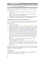
4. Advance the plunger screw until the switch actuates, then advance the
plunger screw an additional 60° (one flat).
5. Exercise the switch roller up and down the cam to verify consistent on/
off operation. Advance the stop screw to touch the switch, then back out
the screw 1.5 turns (9 flats).
Calibration Procedure
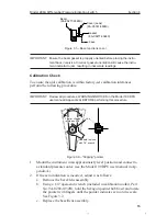
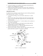
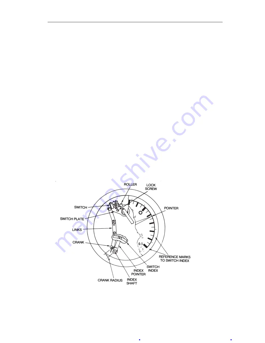
To calibrate the switch linkage (required when the unit is rebuilt), perform the
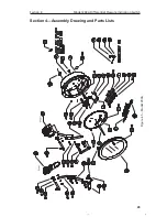
following steps. Refer to Figure 3.7 as needed.
1. Loosen the three linkage screws and turn the crank to the 12 o’clock
position.
2. Use a 1/8-inch Allen wrench to hold the index shaft and slip the index
pointer to 0 on the switch index. Tighten the screw on the crank to the
mid-slot position.
3. Turn the switch index pointer to “1” (index numbers refer to numbers on
outer edge of scale plate).
4. Apply 10% differential pressure and adjust the switch plate until the
switch actuates. Lock the two linkage screws.
5. Rotate the index pointer to “9.” Apply 90% differential pressure and
adjust the crank radius until the switch actuates.
6. Recheck 10% and 90% set points. Adjust the crank radius and the index
pointer until both set points are 2% accurate (nominal).
Figure 3.7—Linkage arrangement
Содержание BARTON 289A
Страница 75: ...R U S S I A ms kl c a m com 603 5569 0501 ...

