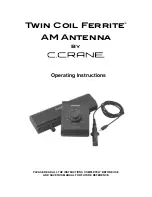
DRAFT 02
1. Select an area on the roof for the base mount keeping in mind the following
IMPORTANT POINTS
:
a) The antenna must be mounted with the coax channel towards the rear of the vehicle.
b)
The center of the roof hole must be at least 20” away from any object taller than 8” to provide clearance for the
antenna head. The center of the roof hole must also be at least 8” from the edge of the roof.
2.
Connect the coax from the power inserter’s antenna input to the coax cable in the base mount.
(The coax may come up thru
the roof or enter thru the coax channel.)
3.
Apply sealant to the base mount, and
fi
ll the coax channel with sealant. Place the base mount in position.
4.
Fasten the base mount to the roof. Make sure the base mount is sealed all the way around. Make sure the coax channel and
fastener heads are sealed as well.
IMPORTANT! The installer is responsible for determining and supplying the most appropriate fasteners to
secure the antenna to the roof, and for weatherproo
fi
ng all holes with roof-compatible sealant.
All holes and fastener heads must be sealed so they are completely waterproof.
IMPORTANT!
Sealant must be compatible
with roof material.
ANTENNA INSTALLATION
SPECIFICATIONS
Power requirement: +12 Volt / 100 mA
Power supplied by: KING Power Inserter
(included with this product)
Enclosure/Mount: ASA-Automotive
grade
SPECIFICATIONS
Dimensions:
23cm H x 33cm W x 33cm L
Weight: 1
kg
Frequency
VHF (54-216 MHz)
Bands:
UHF (470-698 MHz)
FM (87.9-107.9 MHz)
AM (530-1700 KHz)
IMPORTANT!
Coax channel must face
towards rear of vehicle.
Frequency
Bands:
VHF (174 to 230 MHz)
UHF (470 - 698 Mhz)


